Stapling device

a technology of stapling device and staple tip, which is applied in the direction of stapling tools, nailing tools, thin material handling, etc., can solve the problems of poor appearance of staples, deterioration of operability, and productivity decline, so as to reduce the possibility of staple tip end overflow and minimize productivity drop

Active Publication Date: 2008-07-08
FUJIFILM BUSINESS INNOVATION CORP
View PDF6 Cites 16 Cited by
  • Summary
  • Abstract
  • Description
  • Claims
  • Application Information

AI Technical Summary

Benefits of technology

[0009]In view of the above circumstances, the present invention provides a stapling device that achieves both a reduction in the possibility of occurrence of overflow of staple tip ends from a receiving section and minimization of a drop in productivity.

Problems solved by technology

Of such stapling devices, a stapling device which fastens pieces of paper with one kind of staple (bent wire) regardless of the number of pieces of paper to be bound suffers a problem of tip ends of the bent staple become too long when the number of pieces of paper to be bound is small, thereby rendering the appearance of the staple poor.
However, this apparatus suffers a problem of operation for replacing staples becoming laborious, which in turn deteriorates operability.
Thus, discarding the staple tip ends for preventing occurrence of overflow of staple tip ends from the receiving section results in deterioration of productivity.
When the staple tip ends received in the receiving section are discarded into the staple recovery box, the stapler unit must temporarily depart from the stapling position, thereby resulting in deterioration of productivity.

Method used


Image

  • Stapling device
  • Stapling device
  • Stapling device

Examples


second embodiment

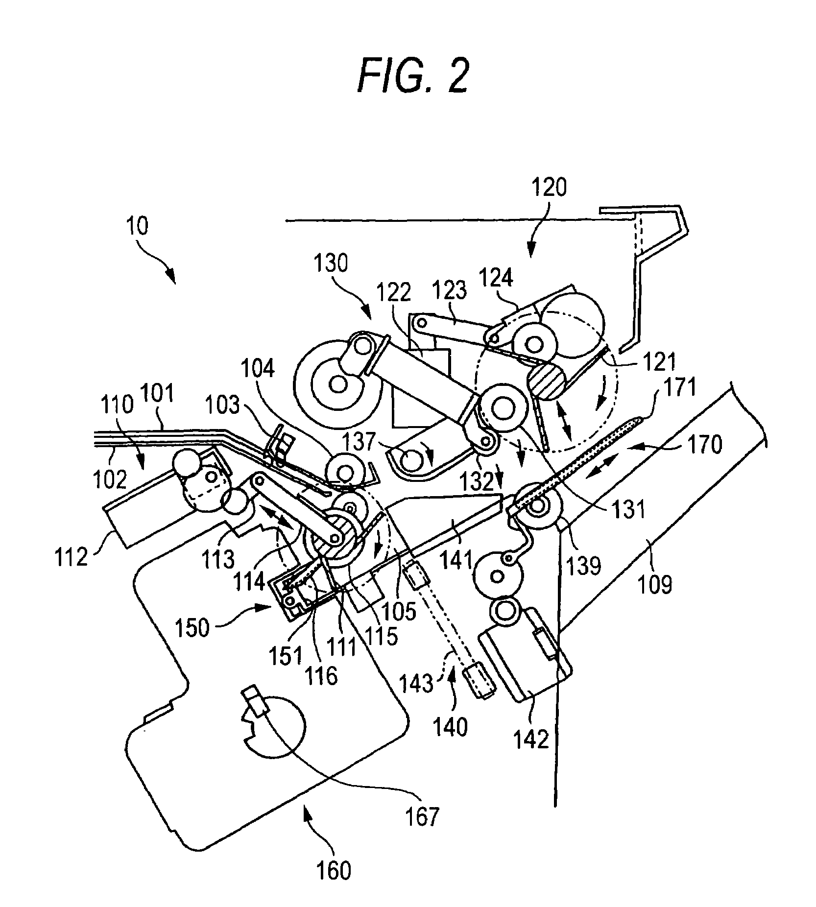
[0099]In the stapling device of the second embodiment, when a set of paper is discharged toward the exit tray 109, the thickness of the set of paper is detected by means of rotation of the eject roller 131 shown in FIG. 2.

[0100]FIG. 16 is a view showing a mechanism for detecting the thickness of a set of paper provided in the stapling device of the second embodiment.

[0101]In addition to showing the rotation center shaft 137 shown in FIG. 2, FIG. 16 shows a driving gear 1371 attached to the rotary center shaft 137 and a driven gear 1372 meshing with the driving gear 1371. A disk 1373 in which are circumferentially formed plural slits 1373a is attached to the rotary shaft of the driven gear 1372. Further, a thickness detection sensor 1374 for detecting the slits 1373a of the disk 1373 is also shown. By utilization of a phenomenon of the number of rotations of the rotary center shaft 137 being changed by the thickness of the set of paper, the thickness detection mechanism shown in FIG....

third embodiment

[0126]According to the stapling device 10 of the third embodiment, operation for counting staple tip ends in the receiving section which varies according to the type of paper is performed. Specifically, the job information acquired by the control section 7 includes information about the type of paper selected by way of the paper type selection screen 520 shown in FIG. 8. The control section 7 performs operation for counting staple tip ends in the receiving section according to the type of paper, by utilization of the information about the type of paper.

[0127]FIG. 23 is a functional block diagram showing a control section when the operation for counting staple tip ends in the receiving section according to the type of paper is performed.

[0128]The control section 7 shown in FIG. 23 includes a staple waste counter section 731 for counting the number of staple tip ends to be held in the receiving section while incrementing or decrementing a count value according to the thickness of a se...

fourth embodiment

[0147]FIG. 27 is a view showing a receiving section of the stapling device of the

[0148]A fullness detection sensor 1635 is shown in the receiving section 163 shown in FIG. 27. The fullness detection sensor 1635 has a phototransmission section 1635a and a light-receiving section 1635b. As a result of staple tip ends being stored in the receiving section 163 to thus block the light emitted from the phototransmission section 1635a, the light-receiving section 1635b detects that the receiving section 163 is filled with the staple tip ends. On the basis of the detection result output from the fullness detection sensor 1635, the control section 7 moves the stapler unit 160 to the staple discarding position.

[0149]A stapling device of a fifth embodiment will now be described. Even in this embodiment, constituent elements which are the same as those of the stapling device of the first embodiment are assigned the same reference numerals that have been used thus far, and the drawings that have...


PUM


Abstract

A stapler unit has a staple section, a cutter section, and a receiving section. A stapling device further includes a staple recovery box which is disposed at a staple discarding position and which recovers the tip ends to be discarded from the receiving section; and a staple discarding mechanism which delivers the tip ends received in the receiving section of the stapler unit to the staple recovery box. One of the plural stapling positions is identical with the staple discarding position.

Description

BACKGROUND OF THE INVENTION[0001]1. Field of the Invention[0002]The present invention relates to a stapling device equipped with a stapler unit which travels along a path including a staple discarding position and plural stapling positions and performs stapling operation for fastening one position on plural stacked sheets.[0003]2. Description of the Related Art[0004]The above-described stapling device has hitherto been known. Of such stapling devices, a stapling device which fastens pieces of paper with one kind of staple (bent wire) regardless of the number of pieces of paper to be bound suffers a problem of tip ends of the bent staple become too long when the number of pieces of paper to be bound is small, thereby rendering the appearance of the staple poor.[0005]In an attempt to solve the problem, there has been proposed a stapling device which offers staples of different lengths and replaces one kind of staple with another kind of staple in accordance with the number of pieces o...

Claims


Application Information

Patent Timeline
Patent Type & Authority Patents(United States)
IPC IPC(8): B65H37/04
CPCB27F7/006B27F7/21B65H37/04B65H2801/31B65H2801/27
Inventor SATO, RYUICHITAKAISHI, YOSHIYUKI
Owner FUJIFILM BUSINESS INNOVATION CORP
Why Eureka
Try Eureka