
Coaxial connector inner contact arrangement

a technology of inner contact arrangement and coaxial connector, which is applied in the direction of coupling device connection, two-part coupling device, electrical apparatus, etc., can solve the problems of increasing assembly difficulty, increasing the chance of generation of passive intermodulation (pim) distortion, and discontinuous impedan

Inactive Publication Date: 2009-11-24
COMMSCOPE INC
View PDF18 Cites 18 Cited by
  • Summary
  • Abstract
  • Description
  • Claims
  • Application Information

AI Technical Summary

Benefits of technology

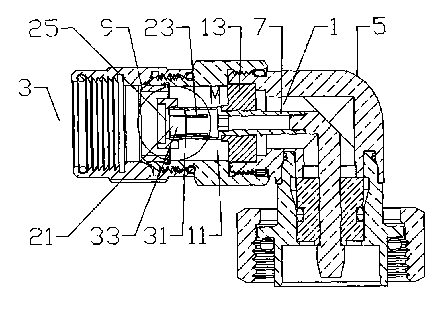
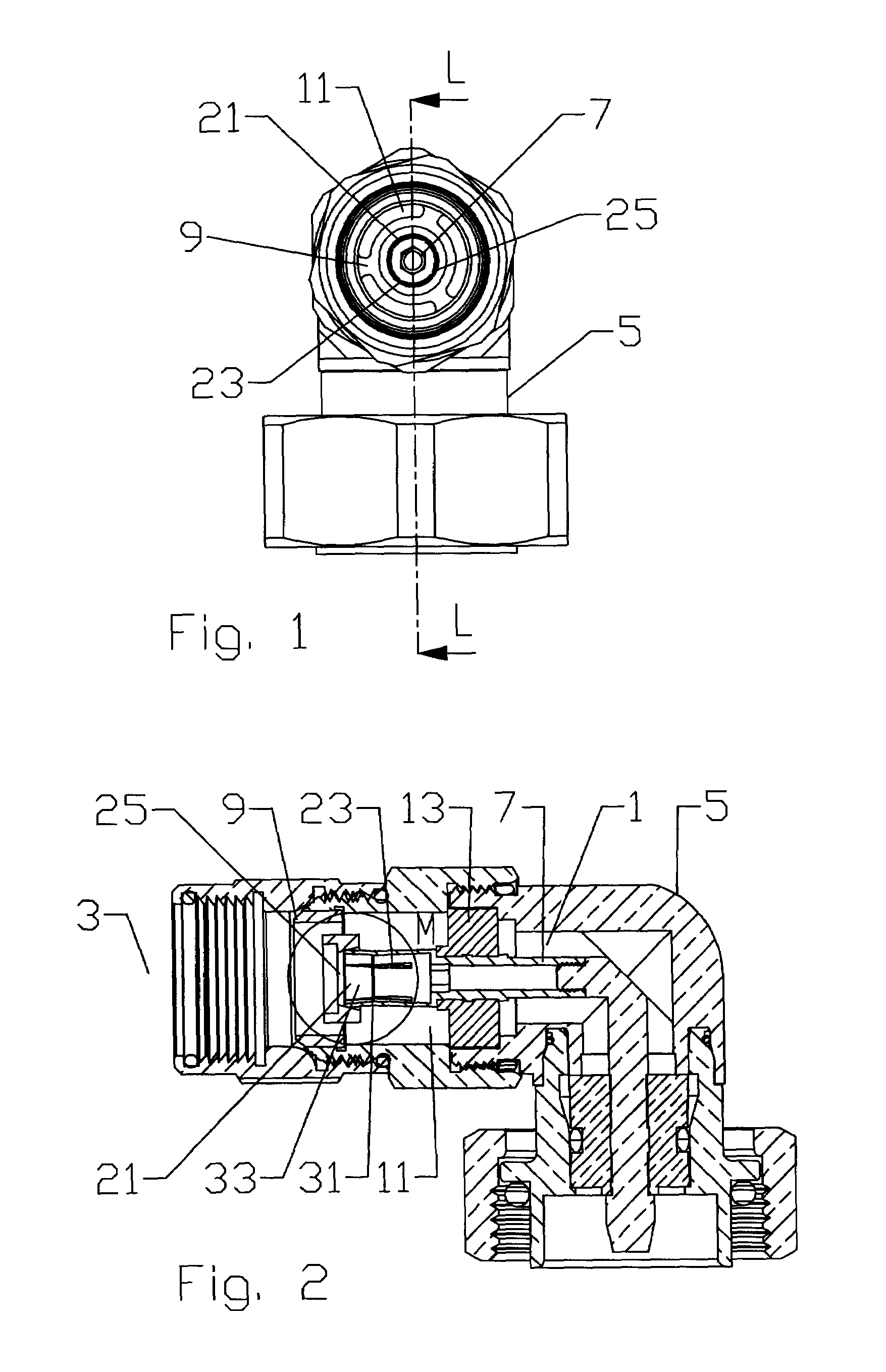
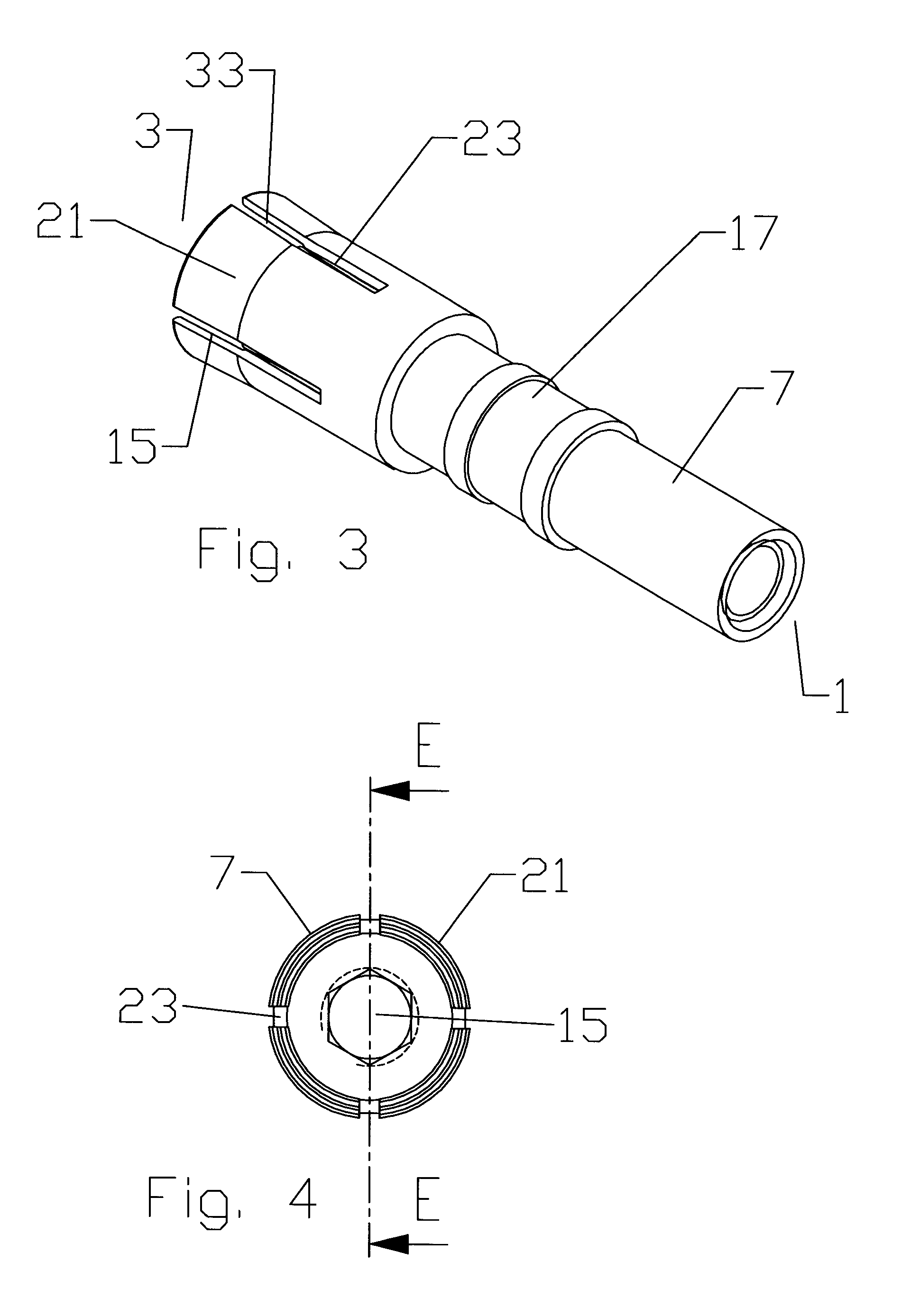
[0028]As shown in FIGS. 8-10, during inner conductor 19 insertion into the spring basket 15 the inner conductor 19 is guided and centered by the guide surface 33. Rather than abutting the end of a spring basket 15 that requires the full insertion force to move past the first point of contact, insertion resistance gradually increases as the inner conductor moves along the guide surface 33 approaching the shoulder 31. The gradual nature of the guide surface 33 also enables insertion with reduced binding of an inner conductor 19 that has not been chamfered, simplifying the cable preparation requirements. Because of the graduated increase in required insertion force, scraping of the inner conductor 19 by the tine(s) 21 along the full insertion length may be reduced, thereby reducing the possibility of generating metal shaving(s) associated with PIM distortion.
[0038]The invention provides a cost effective inner contact with improved electrical performance and increased cable dimensional variation compatibility. Further, the inner contact does not require the swaging operation during manufacture that is typical of the prior inner contacts, reducing the cost of manufacture.

Problems solved by technology

Spring fingers, alone, provide an interconnection with the inner conductor having limited strength characteristics, unless the spring fingers are dimensionally large, which introduces an impedance discontinuity to the resulting connector.
Further, assembly becomes increasingly difficult as the spring finger inward bias is increased to achieve a correspondingly stronger interconnection with the inner conductor.
Also, high bias spring fingers increase the possibility that the spring fingers will scrape the inner conductor during insertion, which increases the chance for generation of passive intermodulation (PIM) distortion.

Method used


Image

  • Coaxial connector inner contact arrangement
  • Coaxial connector inner contact arrangement
  • Coaxial connector inner contact arrangement

Examples


Embodiment Construction

[0022]Connector end 1 and cable end 3 are each applied herein as side identifications for individual elements of the connector 5 along a path through the connector 5 between the cable connection and an interface of the connector, to provide position references for element features described and inter-element contacting surface clarification.

[0023]Analyzing the prior inner contact 7 configurations, the inventor has recognized several drawbacks of a movable insulator as a bias mechanism for the inner contact. Dimensional variations of outer conductors of different materials, production runs and or manufacturer's may be significant. Also, the shape of the flare applied to the outer conductor is dependent upon the specific flare tool used and flaring force that is applied. Because of the wide range of these variances, the final longitudinal position of the movable insulator may vary significantly when the connector is assembled, resulting in a varying degree of inward bias by the spring...


PUM


Abstract

An inner contact arrangement for a coaxial cable connector. The inner contact supported coaxially within a connector bore of the connector by a support insulator. A plurality of tines extending from a central portion of the inner contact, the tines may be angled outward from a longitudinal axis of the inner contact and or provided with a shoulder. A bias insulator with a ramp bore, the bias insulator retained within the connector bore and contacting the cable end of the tines.

Description

BACKGROUND OF THE INVENTION[0001]1. Field of the Invention[0002]The invention relates to connectors for coaxial cable. More particularly the invention relates to an inner conductor contact arrangement with improved inner conductor dimensional variance capacity, assembly characteristics and electrical performance.[0003]2. Description of Related Art[0004]The inner conductor contact of a coaxial connector couples with the inner conductor of a coaxial cable. Surrounded by the connector body and / or mechanical connections between the connector body and the outer conductor of the coaxial cable, the inner conductor contact is typically formed with a plurality of spring fingers biased inward to securely grasp the outer diameter of the inner conductor as it is inserted between them during interconnection of the connector and cable.[0005]Spring fingers, alone, provide an interconnection with the inner conductor having limited strength characteristics, unless the spring fingers are dimensionall...

Claims


Application Information

Patent Timeline
Patent Type & Authority Patents(United States)
IPC IPC(8): H01R9/05H01R24/38H01R24/86
CPCH01R9/0521H01R24/545H01R2103/00
Inventor PAYNTER, JEFFREYWLOS, JAMES
Owner COMMSCOPE INC
Learn More