Inspecting method and inspecting device of control signal for display device, and display unit having this inspecting function

Inactive Publication Date: 2008-07-08
PANASONIC LIQUID CRYSTAL DISPLAY CO LTD +1
View PDF5 Cites 4 Cited by
  • Summary
  • Abstract
  • Description
  • Claims
  • Application Information

AI Technical Summary

Benefits of technology

[0006]An object of the present invention is to provide a method of inspection and a device for inspection of a control signal for a display device, which make it possible to simply inspect the states of various kinds of timing signals (control signals), such as the horizontal synchronizing signal (HSYNC), the vertical synchronizing signal (VSYNC), the display timing signal (DTMG), etc., that are supplied from the external signal source to the display device, and also to provide a display unit having this inspecting function.

Problems solved by technology

However, in using these techniques, it is impossible to determine the detailed contents of the abnormality of the control signal.

Method used


Image

  • Inspecting method and inspecting device of control signal for display device, and display unit having this inspecting function
  • Inspecting method and inspecting device of control signal for display device, and display unit having this inspecting function
  • Inspecting method and inspecting device of control signal for display device, and display unit having this inspecting function

Examples


Embodiment Construction

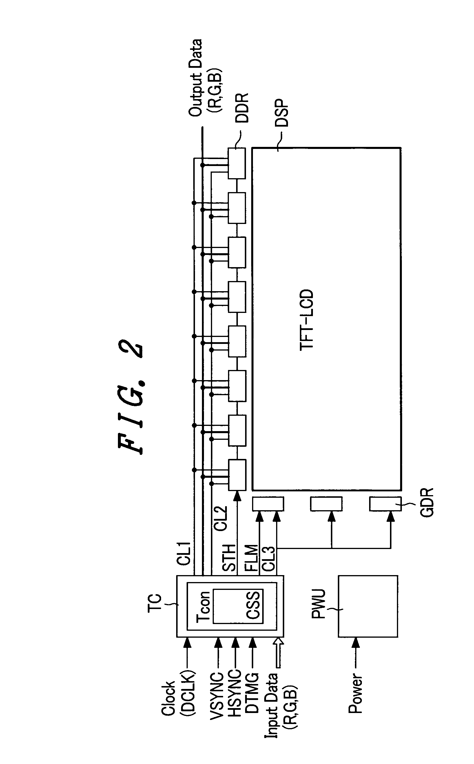
[0034]Various embodiments of the present invention will be explained in detail with reference to the drawings. FIG. 2 is a block diagram of the construction of a display device in accordance with the present invention, with a display unit using a liquid crystal panel serving as an example. However, the present invention is not limited to a liquid crystal display unit using a liquid crystal panel, but also can be applied to a display unit using a display device for performing a similar operation to produce a display. FIGS. 3 and 4 are basic operation waveform charts of a control signal for operating the liquid crystal display unit shown in FIG. 2, where FIG. 3 shows the waveform chart of horizontal direction operation timing and FIG. 4 shows the waveform chart of vertical direction operation timing.

[0035]The construction of FIG. 2 will be explained with reference to FIGS. 3 and 4. First, in FIG. 2, reference numerals TFT-LCD and TC respectively designate a liquid crystal panel operat...


PUM


Abstract

The states of various kinds of control signals, such as a horizontal synchronizing signal, a vertical synchronizing signal, a display timing signal, etc., that are supplied from an external signal source to a display device, are inspected. In the states of various kinds of control signals supplied from the external signal source HOST to the display device DSP, (1) the vertical synchronizing signal (VSYNC) is converted into a display signal of red (R), (2) the horizontal synchronizing signal (HSYNC) is converted into a display signal of green (G), and (3) the display timing signal is converted into a display signal of blue (B) by a control signal inspecting circuit. The states are displayed in color and brightness on the screen of the display device DSP, so that these states can be simply visually inspected.

Description

BACKGROUND OF THE INVENTION[0001]The present invention relates to a flat type display device in the form of a liquid crystal panel, an organic EL panel or a plasma panel, for example, and, more particularly, the invention relates to a method of inspecting control signals for these display devices, and a display unit having this inspecting function.[0002]In an image and screen image display unit using a flat type display device, such as a personal computer or a flat panel type television, for example, various kinds of timing signals serving as control signals for displaying a display signal (an image signal and a screen image signal) on the screen of the display device are supplied from an external signal source (HOST), such as an image processing circuit of a personal computer main body or a screen image signal processing circuit of a television receiver, etc., together with the display signal.[0003]When there is an abnormality in the control signal inputted from the external signal...

Claims


Application Information

Patent Timeline
IPC IPC(8): G09G3/36G02F1/133G02F1/13G09G5/00H04N17/00
CPCG09G5/006F16K11/20F16K27/067F16K37/0016
Inventor IGARASHI, YOICHI
Owner PANASONIC LIQUID CRYSTAL DISPLAY CO LTD
Why Eureka
Try Eureka