Windscreen wiper device

a technology of wipers and wipers, which is applied in the direction of vehicle maintenance, vehicle cleaning, domestic applications, etc., can solve the problems of affecting the stability of the wiper, the play between the oscillating arm and the carrier, and the reliability of the connection to diminish, so as to achieve a simple, durable and solid manner

Active Publication Date: 2008-07-15
TRICO BELGIUM SA
View PDF16 Cites 38 Cited by
  • Summary
  • Abstract
  • Description
  • Claims
  • Application Information

AI Technical Summary

Benefits of technology

[0006]The object of the invention is to overcome these drawbacks of the prior art as indicated above, in particular to provide a windscreen wiper device wherein the carrier and the oscillating arm are interconnected in a simple though durable and solid manner.
[0007]In order to accomplish that objective a windscreen wiper device of the type referred to in the introduction is characterized according to the invention in that said oscillating arm and said carrier are interconnected with the interposition of a joint part, wherein said joint part comprises at least one resilient tongue engaging in a correspondingly shaped hole provided in said oscillating arm. This makes it possible to realize an effectively operating and reliable joint being extremely wear resistant, whilst minimizing the number of parts.
[0011]In another preferred embodiment of a windscreen wiper device according to the invention said oscillating arm has an at least substantially U-shaped cross-section at the location of its connection to said joint part, wherein each leg of said U-shaped cross-section comprises clamping members which engage around longitudinal sides of said joint part that face away from each other. These clamping members being preferably formed as inwardly bended edges of the U-shaped cross-section serve to further enhance the retention of the oscillating arm onto the carrier in vertical direction, that is perpendicular to the longitudinal direction of the oscillating arm.
[0015]In another preferred embodiment of a windscreen wiper device according to the invention said shaft is formed by two protrusions each extending inwardly on a longitudinal side of said carrier. Preferably said protrusions are cylindrical and form two cylindrical bearing surfaces. The two protrusions that function as bearing surfaces are spaced far apart, so that the forces that are exerted on said bearing surfaces will be relatively low.

Problems solved by technology

A disadvantage of such a known windscreen wiper device is that, due to high forces exerted in practice on the connection between the oscillating arm and the carrier, the reliability of said connection appears to diminish with the passage of time, resulting in play between the oscillating arm and the carrier.
Such a play in practice has proven to lead to frictional contact between these parts and therefore leads to wear.

Method used


Image

  • Windscreen wiper device
  • Windscreen wiper device
  • Windscreen wiper device

Examples


Embodiment Construction

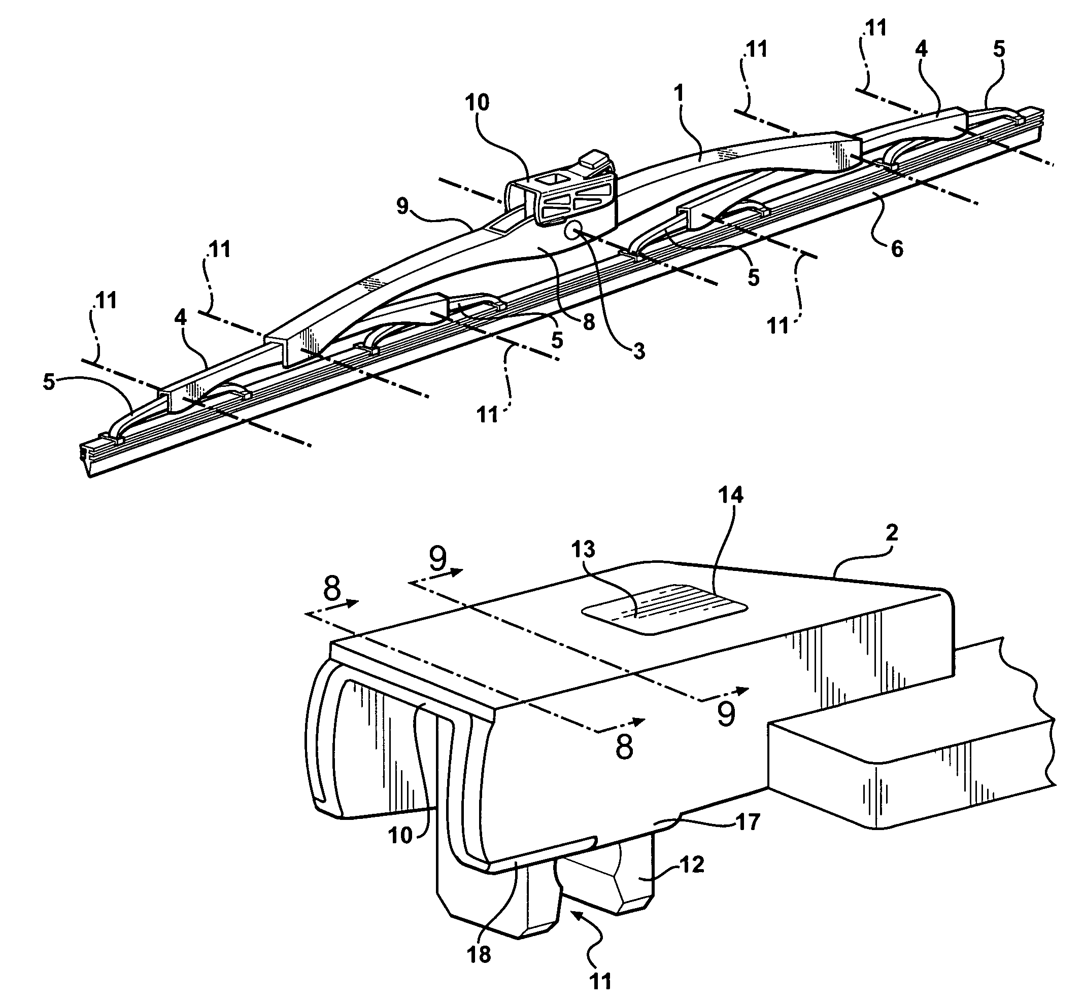
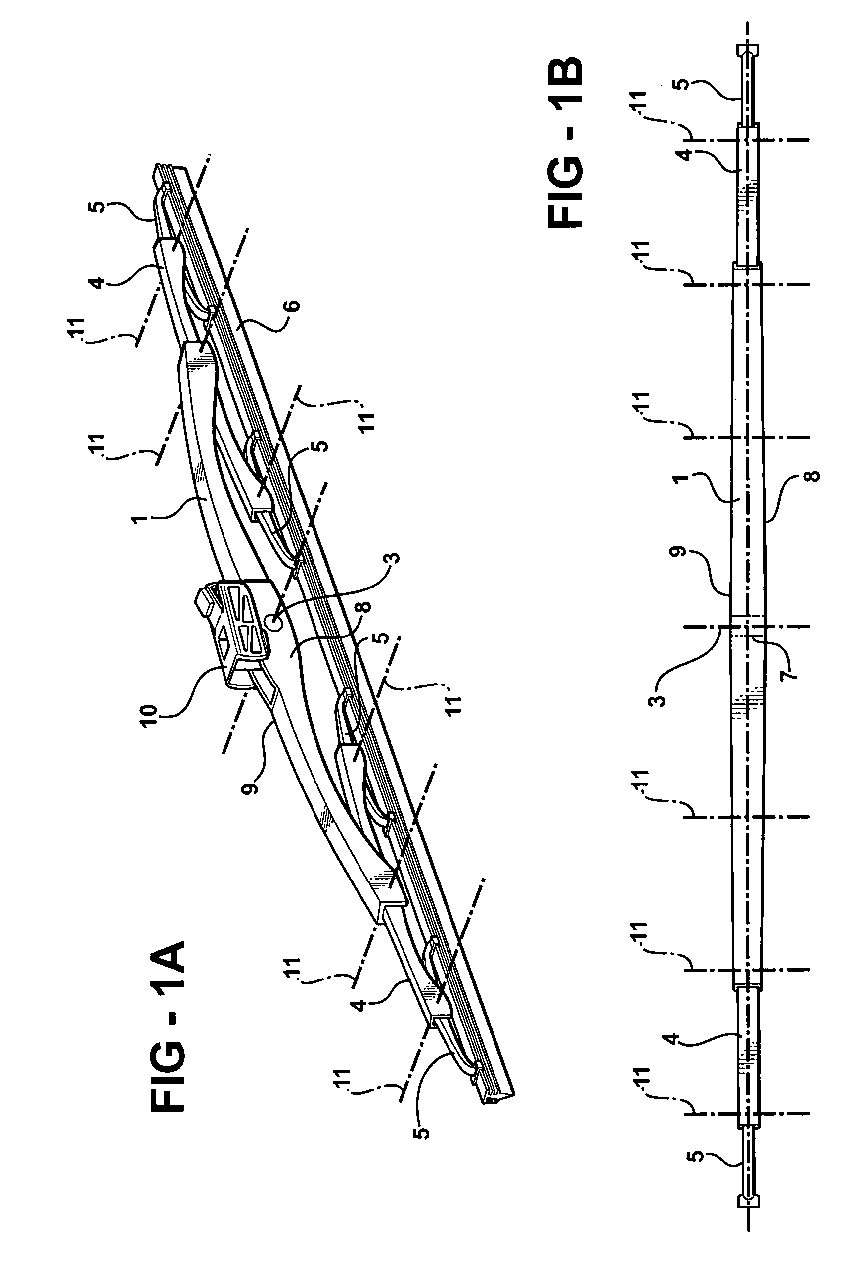
[0027]FIG. 1a shows a perspective view of a windscreen wiper device equipped with a first yoke 1 which can be pivotally attached to an oscillating arm 2 at the location of a pivot axis 3. The first yoke 1 functions as a carrier of two secondary yokes 4, which secondary yokes 4 function as carriers of four tertiary yokes 5. All yokes are pivot-mounted in their respective carriers, such as, for example, pivot axis 11, so that a force exerted at the location of the pivot axis 3 is distributed more or less evenly over the ends of the tertiary yokes 5, capable of being transferred to a rubber wiping element 6, which can be fitted on the ends of the tertiary yokes 5.

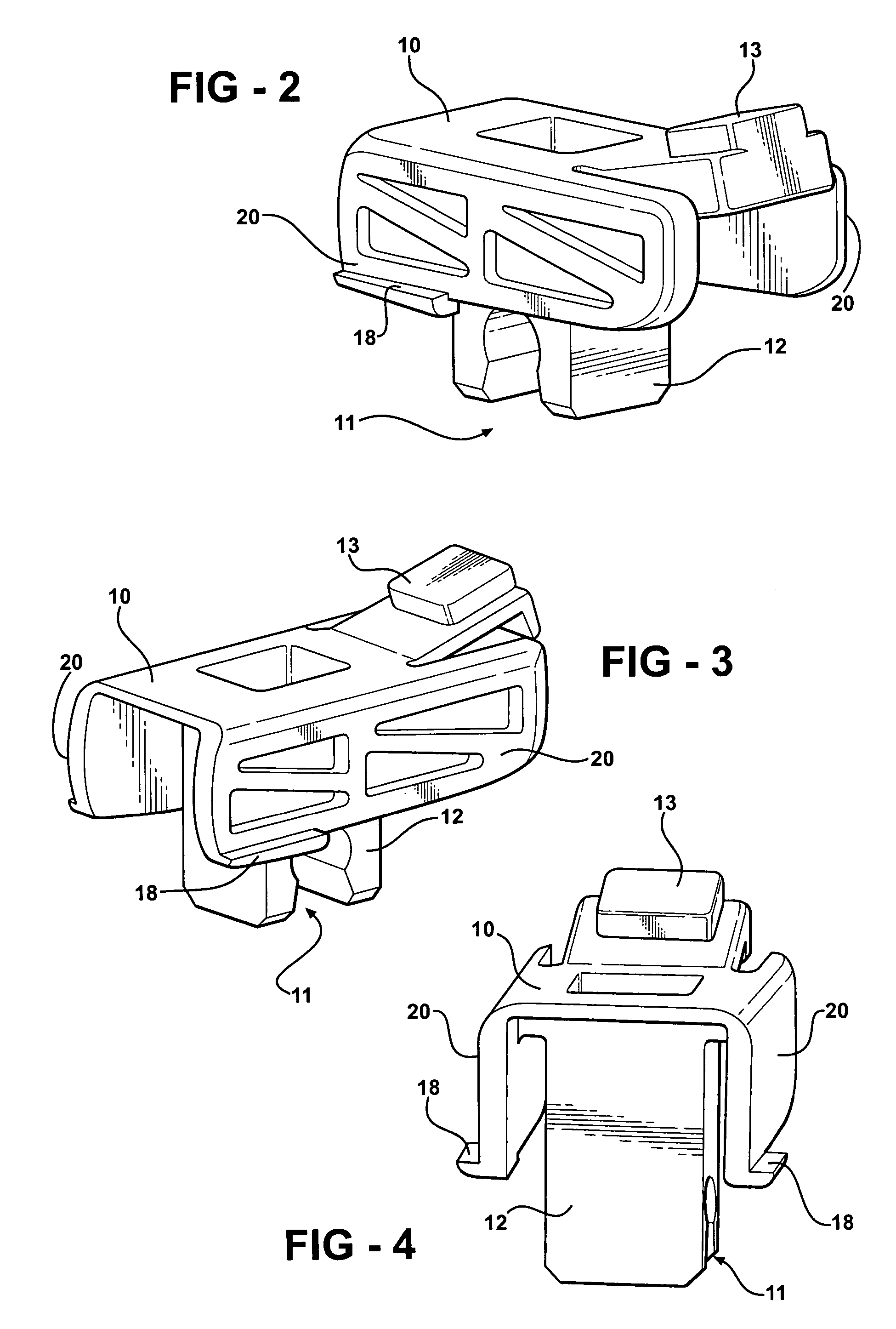
[0028]As can be seen from FIG. 1b, the first yoke 1 is provided, at the location of the pivot axis 3, with a shaft in the form of a transverse pin 7 extending from one longitudinal side 8 to another longitudinal side 9 of the first yoke 1. A joint part 10 is snapped (“clipped”) onto the pin 7, in such a manner that the pin 7 i...


PUM


Abstract

A windscreen wiper device comprising at least one yoke which is attached to a carrier in such a manner as to be capable of pivotating movement about a first pivot axis, wherein both said carrier and said yoke have a substantially U-shaped cross-section at the location of their interconnection, said windscreen wiper device further comprising a oscillating arm pivotally connected to said carrier about a second pivot axis near one end, wherein said carrier is provided, at the location of said second pivot axis, with a transverse shaft, with the special feature that said oscillating arm and said carrier are interconnected with the interposition of a joint part, wherein said joint part comprises at least one resilient tongue engaging in a correspondingly shaped hole provided in said oscillating arm.

Description

BACKGROUND OF THE INVENTION[0001]1. Technical Field[0002]The present invention is related generally to windscreen wiper devices. More particularly, the invention relates a windscreen wiper device having a joint part for interconnecting a carrier of the windscreen wiper device with an oscillating wind screen wiper arm.[0003]2. Related Art[0004]A windscreen wiper device of this type is generally known and is usually provided with a plurality of yokes, in order to ensure that a wiper blade thereof is in contact with a, usually curved, windscreen along its entire length. Each yoke is thereby pivoted to the end of a carrier in its central portion, which carrier itself may also be a yoke. Usually said carrier and yoke(s) are made of metal, so that a plastic part often called “spacer” is interposed at the location of the connection of a carrier and a yoke, said plastic part being stationary with respect to a carrier associated therewith. The oscillating arm has a hook-shaped end hooking up...

Claims


Application Information

Patent Timeline
Patent Type & Authority Patents(United States)
IPC IPC(8): B60S1/40
CPCB60S1/4038B60S2001/4054B60S2001/4051B60S2001/3813
Inventor GENET, SOPHIE
Owner TRICO BELGIUM SA
Why Eureka
Try Eureka