Cryogenic seal for vacuum-insulated pipe expansion bellows

a vacuum-insulated pipe and expansion bellow technology, applied in the field of insulated pipes, can solve the problems of cryogenic material leakage from inside the inside pipe into the vacuum area between the inner and outer pipes, and the arrangement would be prohibitively expensiv

Inactive Publication Date: 2008-07-15
CHART INDS
View PDF6 Cites 6 Cited by
  • Summary
  • Abstract
  • Description
  • Claims
  • Application Information

AI Technical Summary

Problems solved by technology

A major source of thermal leakage in insulated pipe systems is at the junction between two pipe sections.
Such an arrangement would be prohibitively expensive.
A disadvantage associated with existing vacuum-insulated piping is that failures of the bellows of the piping can cause cryogenic material to leak from within the inside pipe into the vacuum area between the inner and outer pipes.
Vaporization of the leaked liquid cryogenic material and the cooling effects of the cryogenic material on the outer pipe can create a situation where other parts of the pipe spool system may fail catastrophically.
Additionally, leakage of cryogenic material from the inside pipe results in safety concerns and the loss of saleable product.

Method used


Image

  • Cryogenic seal for vacuum-insulated pipe expansion bellows
  • Cryogenic seal for vacuum-insulated pipe expansion bellows
  • Cryogenic seal for vacuum-insulated pipe expansion bellows

Examples


first embodiment

[0039]In the first embodiment shown in FIG. 5A, a leak control ring 100 is placed between the flange or movable bellows ring 34 and the wall of the female bayonet 22, which serves as a bellows guide. The movable bellows ring 34 may be indented to accept the leak control ring 100.

second embodiment

[0040]In the second embodiment shown in FIG. 5B, an additional leak control ring 102 is placed around the inner pipe 16 of the male bayonet 20. The leak control ring 102 can be placed to circumscribe the inner pipe 16 in a position beneath the fixed bellows ring 44. The fixed bellows ring 44 may be indented to accept the leak control ring 102. The fit between the leak control ring 102 and the fixed bellows ring 44 can be sufficiently loose to allow evacuation of the interior side of the bellows 24 during normal operation, and to allow controlled leakage of cryogenic material during a failure condition.

[0041]The leak control rings 100, 102 may be made of a fluorocarbon polymer, for example TEFLON. Alternatively, the leak control rings 100, 102 may be made of any other suitable material. The leak control rings 100, 102 may have any suitable dimensions. For example, the leak control rings 100, 102 can have a width of approximately 1 inch and a thickness of approximately ¼ inch. Additio...

third embodiment

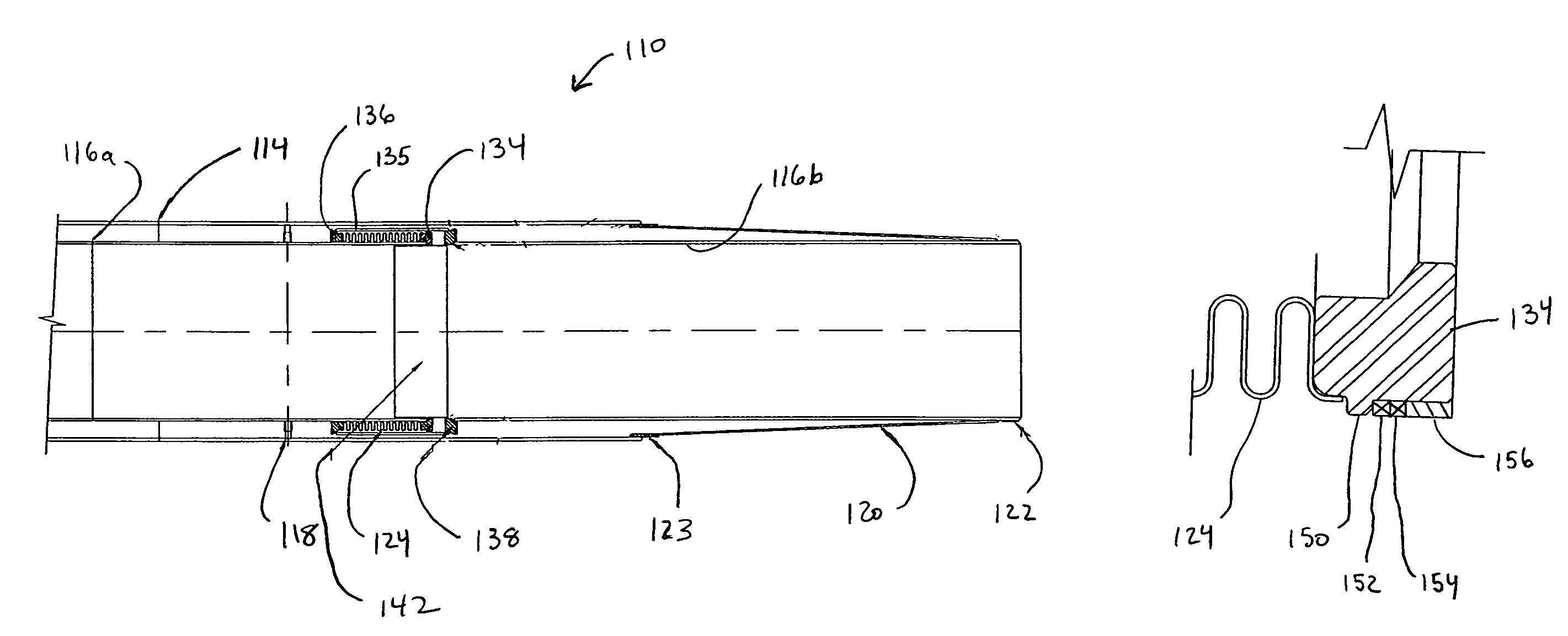
[0043]A portion of a vacuum-insulated pipe incorporating the cryogenic seal of the present invention is indicated in general at 110 in FIG. 7. The pipe features an outer pipe 114 and an inner pipe with sections 116a and 116b. The inner pipe section 116a is positioned within the outer pipe 114 via guide pins 118. A tapered cone 120 is connected between the inner pipe section 116b and outer pipe via inner cone splicing ring 122 and outer cone splicing ring 123.

[0044]As illustrated in FIGS. 7 and 8, a bellows 124 is secured to inner pipe section 116a on one end by movable bellows ring 134. The opposite end of bellows 124 is secured to a bellows guide 135 via first fixed bellows ring 136.

[0045]As illustrated in FIG. 7, an inner piper section 116b is secured to bellows guide 135 by second fixed bellows ring 138. A bellows shield 142 is also attached to the second fixed bellows ring 138 and smoothes the flow of liquid between inner pipe section 116a and 116b. The bellows shield 142 is not...


PUM


Abstract

A cryogenic seal for vacuum-insulated pipe systems where the pipe system includes an inner pipe connected to an outer pipe by a bellows. The seal prevents cryogenic liquid from leaking from the inner pipe into the annular vacuum space between the inner and outer pipes in the event of bellows failure. One end of the bellows is connected to the inner pipe by a movable bellows ring and the other end of the bellows is attached to the outer pipe by a fixed bellows ring. A bellows guide is attached to the fixed bellows ring and receives the movable bellows ring in a sliding fashion. The seal may be positioned between the movable bellows ring and the bellows guide or between the fixed bellows ring and the outer surface of the inner pipe. The seal may also be positioned between the bellows shield and the movable bellows ring. The seal may be a leak control ring or the packed gland type.

Description

CLAIM OF PRIORITY[0001]This application claims priority from U.S. Provisional Patent Application No. 60 / 589,449 filed Jul. 20, 2004.BACKGROUND[0002]The invention relates generally to insulated piping and, in particular, to a cryogenic seal for a vacuum-insulated pipe expansion bellows.[0003]Thermally insulated pipes have a wide variety of industrial applications. For example, insulated piping is used to transport cryogenic liquids, that is, liquids having a boiling point at a temperature below −150° F. at atmospheric pressure, between storage tanks or between a storage tank and a use device. Other examples include utilization in chemical plants or petroleum refining.[0004]A major source of thermal leakage in insulated pipe systems is at the junction between two pipe sections. It is therefore preferable to eliminate such pipe joints. This would require, however, that the insulating piping be custom-manufactured to fulfill the length requirements of specific applications. Such an arra...

Claims


Application Information

Patent Timeline
Patent Type & Authority Patents(United States)
IPC IPC(8): F16L7/00
CPCF16L27/11F16L39/00F16L59/18F16L59/141F16L59/065Y10S285/904
Inventor MOTEW, STUARTMCWILLIAMS, DAVIDDUCOTE, DOUGLASMIDDLETON, WILLIAMBONN, JOHN
Owner CHART INDS
Why Eureka
Try Eureka