Connecting device

a technology of connecting device and contact, which is applied in the direction of coupling device connection, coupling device details, electric discharge lamps, etc., can solve the problems of contact failure and short circuit, and achieve the effect of preventing dust invasion, preventing connection failure of contact or short circuit in the body

Inactive Publication Date: 2008-07-15
HOSIDEN CORP
View PDF15 Cites 14 Cited by
  • Summary
  • Abstract
  • Description
  • Claims
  • Application Information

AI Technical Summary

Benefits of technology

[0009]Such a connecting device as mentioned above is hoped to allow the insertion / removal of a lead terminal from its side, at the request for easy insertion / removal of the lead terminal and prevention of breakage of the lead terminal or the entire cold cathode fluorescent lamp during mounting. To adapt the connecting device to allow insertion / removal of the lead terminal from its side, it is necessary to form an insertion opening to insert / remove the lead terminal in the top face of the body. Such an insertion opening in the top face of the body may easily allow invasion of dust, causing a problem such as contact failure of the contact and short circuit.
[0010]The present invention has been made in view of the above situation to provide a connecting device that has an insertion opening for insertion and removal of a lead terminal from its side but still can prevent invasion of dust through the insertion opening.
[0012]Particularly, since the insertion opening can be closed with the shutter, invasion of dust can be prevented.
[0017]By simply operating the operation member as described above, open / close of the shutter and open / close of the space between the first and second hold parts of the first and second clamp arms of the contact can be performed at the same time. Therefore, the shutter will not hinder the insertion of the lead terminal into the insertion opening, and there is no need to perform an operation to open / close the shutter separately from the operation to open / close of the space between the first and second hold parts. Therefore, even though a shutter is provided to keep dust out of the device, it is possible to connect the lead terminal with the contact easily. Further, elastic forces of the first and second clamp arms are only used for holding the lead terminal, so the elastic forces of the clamp arms will not directly act on the body. Moreover, since it is only necessary to insert the lead terminal into the space formed between the first and second hold parts, unlike the third connecting device as described above as a conventional art, it is not needed to form a space for inserting the lead terminal by pressing the contact which is a coil spring with the lead terminal. Therefore, the lead terminal or the electronic components of the invention will not be damaged by the pressing.
[0019]By simply operating the operation member as described above, open / close of the shutter and open / close of the space between the hold part of the second clamp arm and the first clamp arm of the contact can be performed at the same time. Therefore, the shutter will not hinder the insertion of the lead terminal into the insertion opening, and there is no need to perform an operation to open / close the shutter separately from open / close between the hold part of the second clamp arm and the first clamp arm. Therefore, even though a shutter is provided to keep dust out of the device, it is possible to connect the lead terminal with the contact easily. Further, elastic force of the second clamp arm is only used for holding the lead terminal, so a load due to the elastic force of the second clamp arm will not directly act on the body. Moreover, since it is only necessary to insert the lead terminal into the space formed between the hold part of the second clamp arm and the first clamp arm, unlike the third connecting device as described above as a conventional art, it is not needed to form a space for inserting the lead terminal by pressing the contact which is a coil spring with the lead terminal. Therefore, the lead terminal or the electronic components of the invention will not be damaged by the pressing.
[0026]According to the connecting device of the present invention, even if an insertion opening enabling a lead terminal to be inserted / removed from a side face thereof is provided in the body, it is possible to prevent invasion of dust from the insertion opening with a shutter. Therefore, a connection failure of a contact or short circuit in the body can be prevented.

Problems solved by technology

Such an insertion opening in the top face of the body may easily allow invasion of dust, causing a problem such as contact failure of the contact and short circuit.

Method used


Image

  • Connecting device
  • Connecting device
  • Connecting device

Examples


Embodiment Construction

[0054]Hereinafter, a connecting device according to an embodiment of the present invention will be described with reference to the drawings.

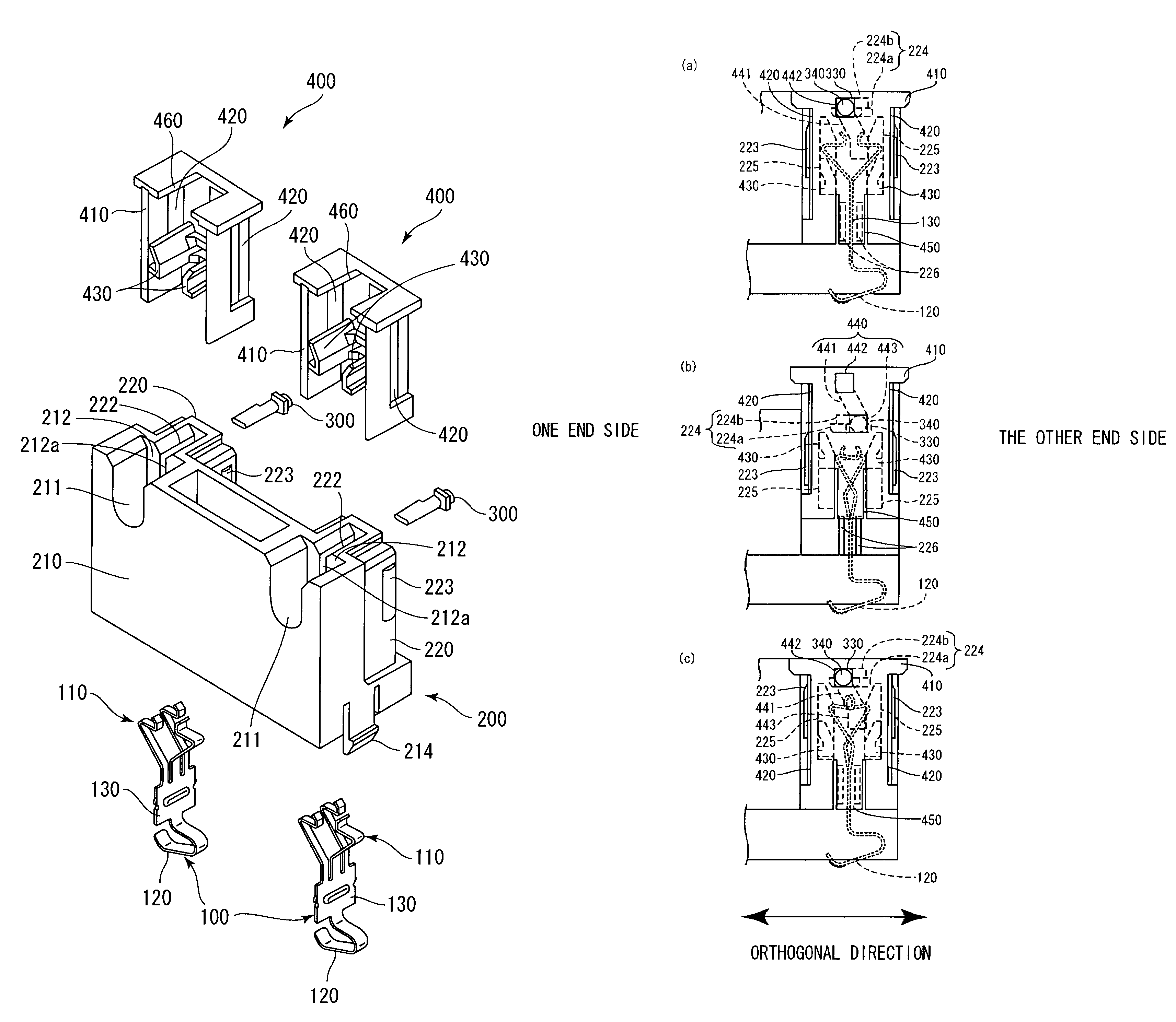
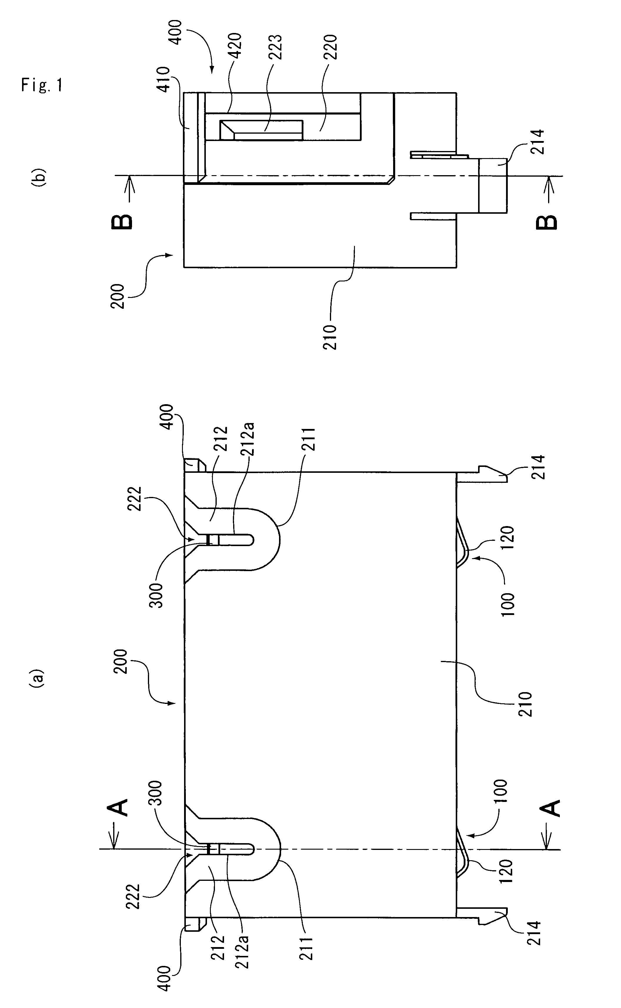
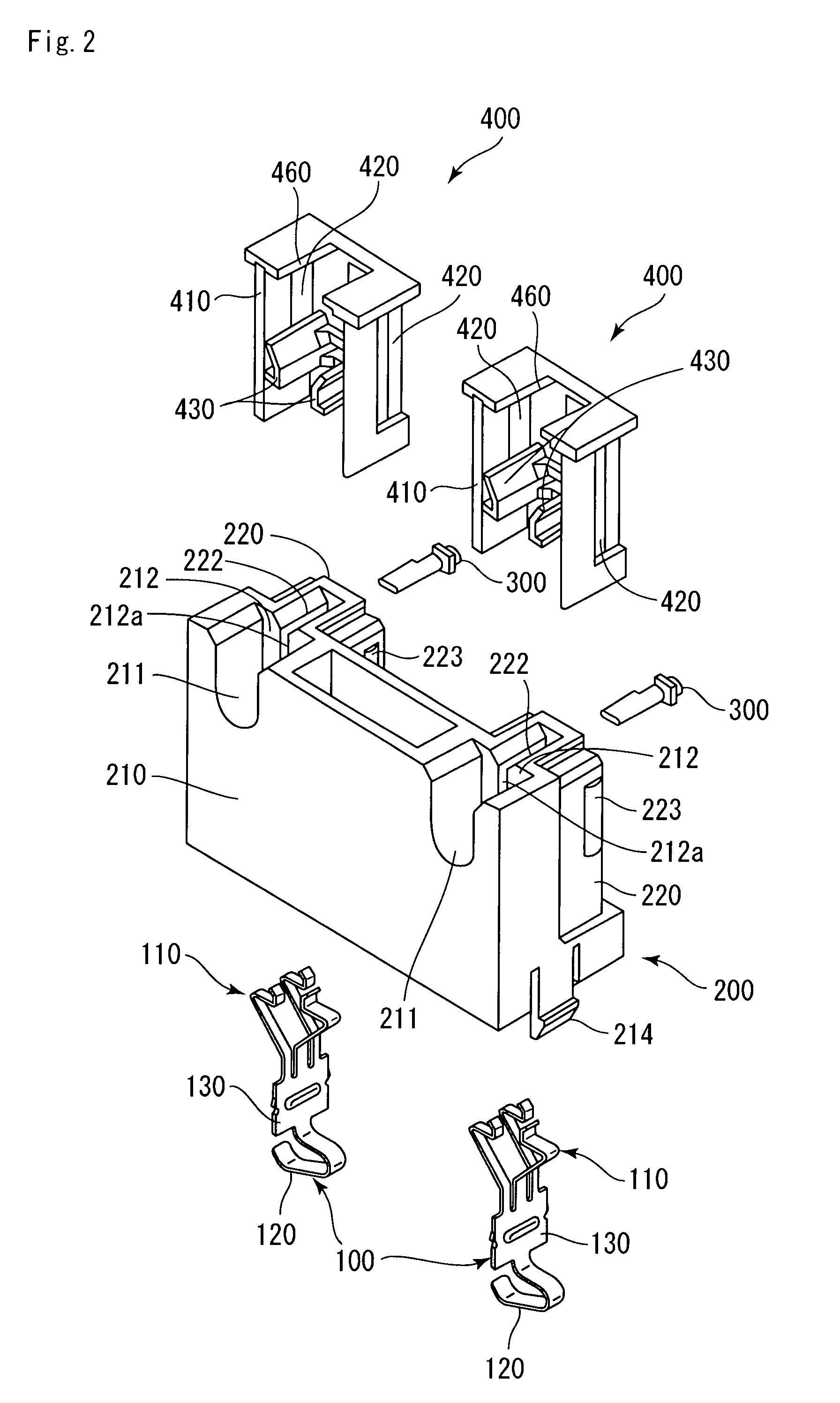
[0055]An embodiment of a connecting device is a socket for a cold cathode fluorescent lamp 10. The socket includes two contacts 100 for electrically connecting a lead terminal 12 of the cold cathode fluorescent lamp (electronic component) 10 and a substrate 20, a body 200 accommodating the two contacts 100 and having a pair of insertion openings 222 to allow insertion / removal of the lead terminal 12 through a side face thereof, a pair of shutters 300 to openably close the pair of insertion openings 222 of the body 200, and a pair of operation members 400 mounted on the body 200 to operate the opening and closing of the pair of shutters 300. Hereinafter, detailed description of the connecting device will be given.

[0056]As shown in FIG. 3, the cold cathode fluorescent lamp 10 includes a lamp part 11 and the lead terminal 12 protruded from the lamp...


PUM


Abstract

A connecting device of the invention includes a contact for electrically connecting with a lead terminal of cold cathode fluorescent lamp (electronic component), a body for accommodating the contact and having an insertion opening to allow the lead terminal to be inserted / removed from a side of the body, a shutter for opening / closing the insertion opening of the body, and an operation member mounted to the body for operating the open / close of the shutter.

Description

[0001]The present application claims priority under 35 U.S.C. §119 of Japanese Patent Application No. 2006-238180 filed on Sep. 1, 2006, the disclosure of which is expressly incorporated by reference herein in its entity.BACKGROUND OF THE INVENTION[0002]1. Field of the Invention[0003]The present invention relates to connecting devices for electrically connecting lead terminals of electronic components such as cold cathode fluorescent lamps.[0004]2. Description of the Related Art[0005]As this kind of connecting device, there is one in which a contact to be accommodated in a body includes a first connection part adapted to elastically hold a lead terminal of a cold cathode fluorescent lamp in between, and a second connection part for connection to a substrate.[0006]For example, as a first connecting device, there is one in which a first connection part includes a fixed piece and a curved movable piece having a rectangular hole into which the fixed piece is inserted. The device is adap...

Claims


Application Information

Patent Timeline
Patent Type & Authority Patents(United States)
IPC IPC(8): H01R33/02
CPCH01R33/9658H01R13/5213H01R4/48H01R9/24
Inventor OHMORI, YASUHIRO
Owner HOSIDEN CORP
Why Eureka
Try Eureka