Blowout preventer testing system

a technology of blowout prevention and testing system, which is applied in the direction of survey, sealing/packing, and wellbore/well accessories, etc., can solve the problems of not rigorously examining, excessive time for pressure stabilization, and drop in pressure, so as to improve the recording, analysis and validation of bop tests. , the effect of improving the quality of the oil and gas

Active Publication Date: 2008-07-22
BP CORP NORTH AMERICA INC
View PDF2 Cites 12 Cited by
  • Summary
  • Abstract
  • Description
  • Claims
  • Application Information

AI Technical Summary

Benefits of technology

[0009]An analysis of real-time pressure / volume / temperature (PVT) data from BOP tests during the pumping and shut-in phases was performed. The PVT behavior that characterizes a valid test and differentiates it from an invalid test (i.e., when there is a leak) was investigated. System response during a valid test for a given configuration (i.e., drillpipe geometry, fluid PVT properties, etc.) should be repeatable and quantifiable. Moreover, the physical mechanisms that govern the observed trends should be identified and explained via the development of a simple theoretical model. Most importantly, the potential impact of this analysis on BOP test methodology was examined. It was theorized that while pressuring up the system, the system was heating up; and subsequently cooling down while holding pressure. As theorized, pressure and temperature gauges confirmed heating up of the fluid in the system as the pressure was increased, and it was evident that the resultant drop in pressure over time was due to the fluid cooling. The excessive time to pressure stabilization was due to the system heat up and subsequent cool down. Real-time digital pressure data during a BOP test allows the operator to differentiate between valid and invalid tests and, simultaneously, reduces the time required to ascertain a valid test.
[0011]Some of the advantages of the invention include simplicity and its speed. Recent advances in digital technology and the relative ease of data processing with inexpensive personal computer (PC) technology lead to a clear opportunity for improvement in the recording, analysis, and validation of BOP tests.

Problems solved by technology

Discussion with rig personnel and engineers indicated that although “pressure decay” was recognized as a characteristic deepwater “phenomenon,” it had not been examined rigorously.
As theorized, pressure and temperature gauges confirmed heating up of the fluid in the system as the pressure was increased, and it was evident that the resultant drop in pressure over time was due to the fluid cooling.
The excessive time to pressure stabilization was due to the system heat up and subsequent cool down.

Method used


Image

  • Blowout preventer testing system
  • Blowout preventer testing system
  • Blowout preventer testing system

Examples


Embodiment Construction

[0028]While this invention is susceptible of embodiment in many different forms, there is shown in the drawings, and will herein be described in detail, one specific embodiment of the invention. It should be understood, however, that the present disclosure is to be considered an exemplification of the principles of the invention and is not intended to limit the invention to any specific embodiment so described.

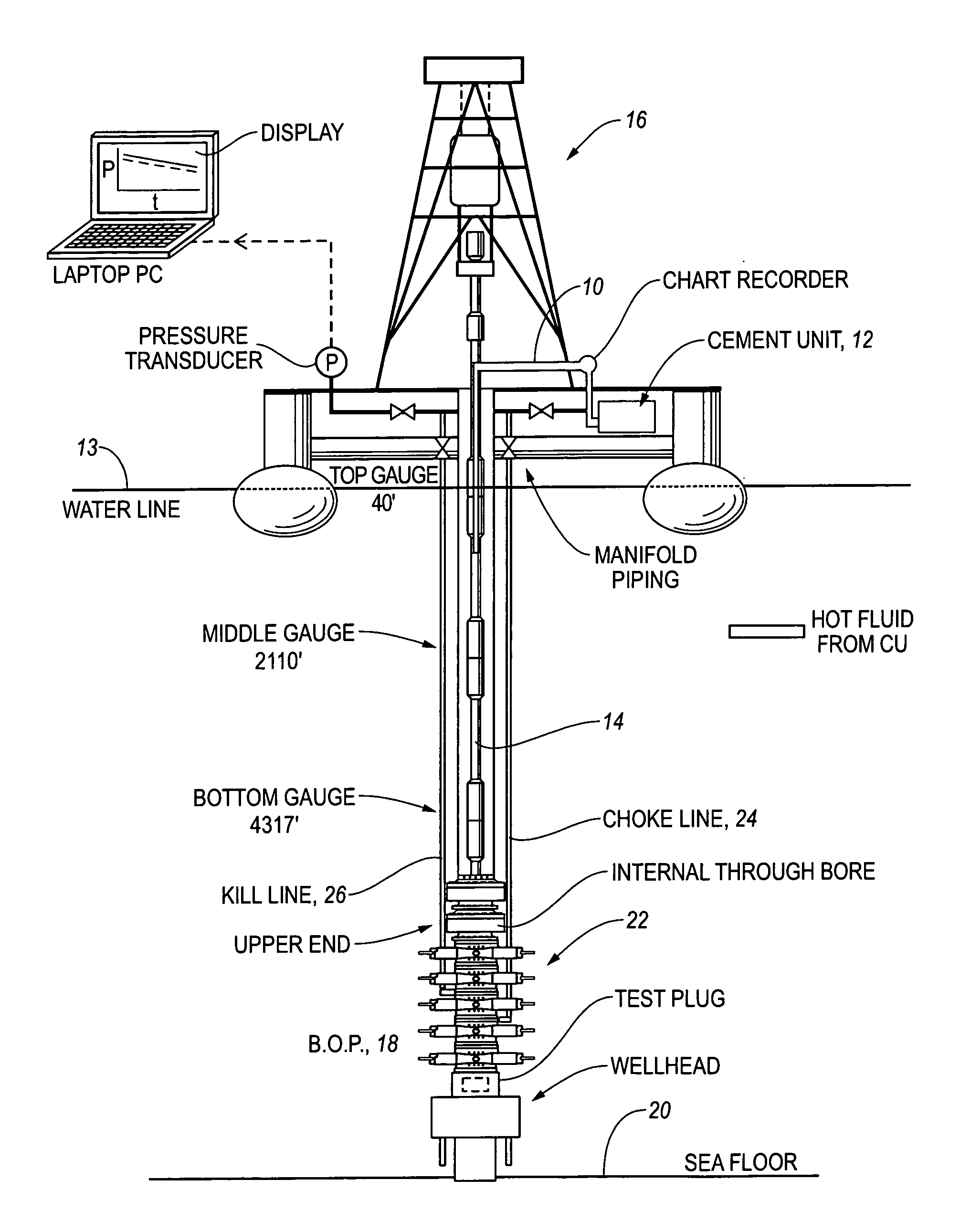
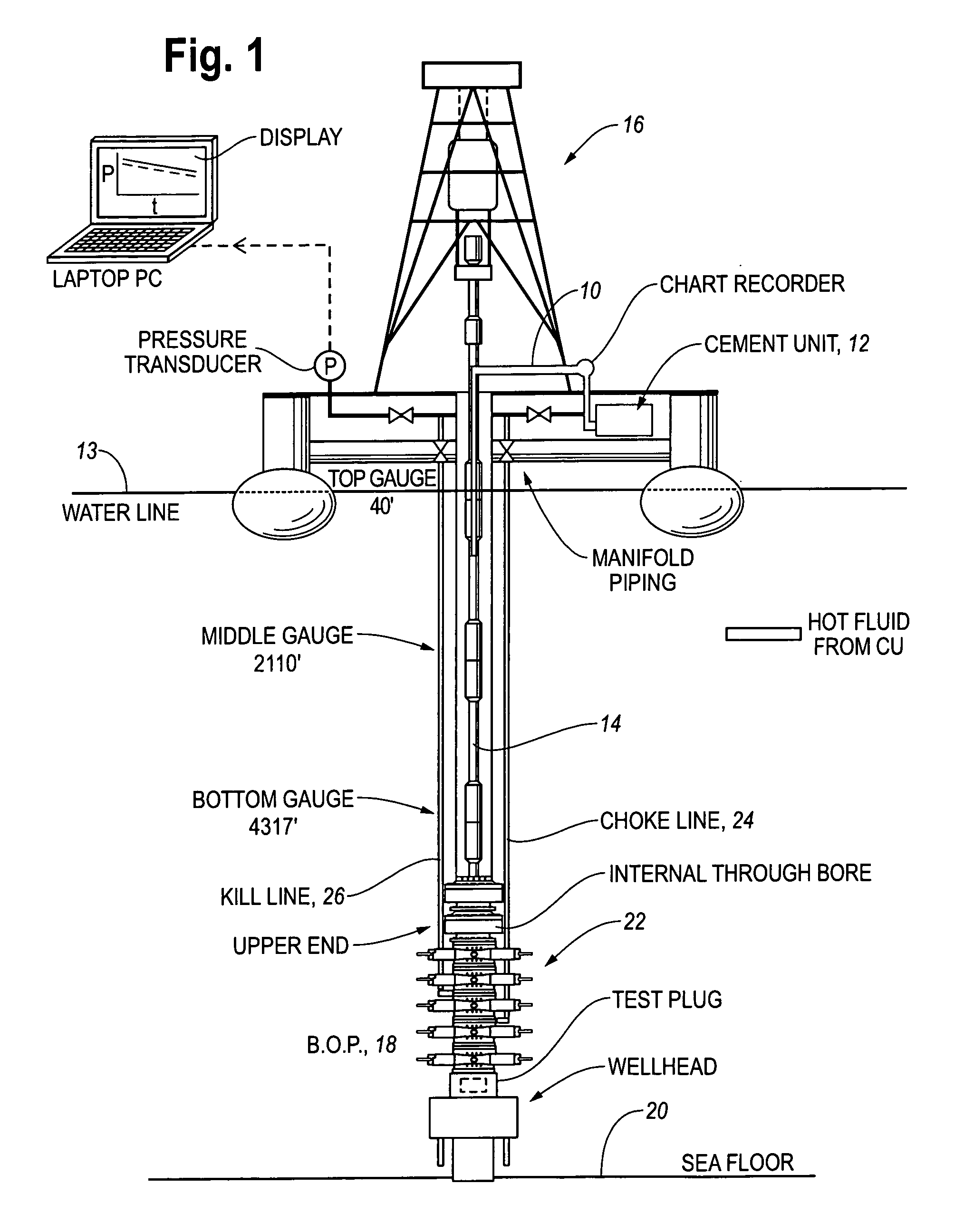
[0029]To understand the P-T response of the system, a series of increasingly complex data acquisition exercises was initiated. In each case, real-time PVT data at different points in the test volume was acquired and analyzed. It was originally hypothesized that the fluid in the test volume is heated by compression and heat transfer from the hot fluid added to the system, i.e., the fluid at the CU discharge is significantly hotter than the fluid in the suction tank. When the pressurized system is shut-in, the subsequent cooling of the fluid causes gradual pressure decay, thus e...


PUM


Abstract

A method and apparatus is disclosed for testing a blowout preventer (BOP) by: using a drillpipe to install a test plug into one end of the throughbore of a (BOP); using a valve in the BOP to isolate the opposite end of the throughbore of the BOP, using piping to connect the output of a cementing unit to the throughbore of the BOP; using the cementing unit to increase the pressure in the throughbore of the BOP to a predetermined level; displaying the pressure in the piping as a function of time; and displaying the pressure in the piping as a function of time for the same blowout preventer system at an earlier time when leakage was deemed to be within predetermined acceptable limits. The pressure decline caused by a leak can be detected reliably and efficiently with high-resolution pressure data.

Description

CROSS-REFERENCE TO RELATED APPLICATIONS[0001]This is a Patent Application claiming the priority of a USA Provisional Patent Application filed on Dec. 26, 2003 under Ser. No. 60 / 532,510 and entitled “Blowout Preventer Testing System”TECHNICAL FIELD[0002]This invention relates to the general subject of production of oil and gas and, in particular to methods and apparatus for testing fluid systems.STATEMENT REGARDING FEDERALLY SPONSORED RESEARCH OR DEVELOPMENT[0003]Not applicableREFERENCE TO A MICROFICHE APPENDIX[0004]Not applicableBACKGROUND OF THE INVENTION[0005]The challenges of obtaining valid Blowout Preventer (BOP) pressure tests in an efficient manner have increased due to greater water depths, deeper drilling horizons, and higher test pressures. FIG. 1 shows the important components involved in testing a subsea BOP stack. A drill string tool or test plug is lowered into the interior or throughbore of the BOP and it seats at the lower end of the BOP to seal off the well componen...

Claims


Application Information

Patent Timeline
Patent Type & Authority Patents(United States)
IPC IPC(8): E21B47/06E21B47/10E21B33/06E21B47/00
CPCE21B47/1025E21B33/06E21B47/117
Inventor FRANKLIN, CHARLES M.
Owner BP CORP NORTH AMERICA INC
Why Eureka
Try Eureka