Method and apparatus for noncontact relative rail displacement, track modulus and stiffness measurement by a moving rail vehicle

a technology of relative rail displacement and track modulus, which is applied in the direction of railway auxilary equipment, instruments, transportation and packaging, etc., can solve the problems of increasing maintenance needs, reducing the life of track components, and low track modulus and large variations in track modulus

Inactive Publication Date: 2008-07-22
BOARD OF RGT UNIV OF NEBRASKA
View PDF3 Cites 63 Cited by
  • Summary
  • Abstract
  • Description
  • Claims
  • Application Information

AI Technical Summary

Problems solved by technology

Both low track modulus and large variations in track modulus are undesirable.
Low track modulus has been shown to cause differential settlement that then increases maintenance needs.
Large variations in track modulus, such as those often found near bridges and crossings, have been shown to increase dynamic loading, which reduces the life of the track components resulting in shorter maintenance cycles.
The economic constraints of both passenger and freight rail service are moving the industry to higher-speed rail vehicles and the performance of high-speed trains are likewise strongly dependent on track modulus.
At high speeds, there is an increase in track deflection caused by larger dynamic forces.
Although these measurements are useful; they are expensive and only are made over short distances (˜tens of meters).
Its major limitation is that it provides only information for a single point along the rail.
Also, slack in the rail can cause non-linearity in the load / deflection relationship.
This further complicates this technique.
The multiple deflection measurements required for this method result in longer traffic delays.
Once again, both heavy and light loads are used to eliminate slack, which further increase the delays.
Both of these methods are time consuming and expensive and all suffer from the major limitation that the measured modulus is only valid along a small length of track.
On-board measurements, however, are difficult because there is no stable reference frame.
And, present on-board systems are labor intensive and move at slow speeds.
Thus, they are limited to short distances (e.g. hundreds of meters) and still interrupt traffic.
The TLV still has limitations.
First, tests are often performed at speeds below 16.1 km / hr (10 mph) so it is difficult to test long section of track (hundreds of miles).
Second, significant expense in both equipment and personnel are required for operation.
For these reasons the TLV has not yet been widely implemented.

Method used


Image

  • Method and apparatus for noncontact relative rail displacement, track modulus and stiffness measurement by a moving rail vehicle
  • Method and apparatus for noncontact relative rail displacement, track modulus and stiffness measurement by a moving rail vehicle
  • Method and apparatus for noncontact relative rail displacement, track modulus and stiffness measurement by a moving rail vehicle

Examples


Embodiment Construction

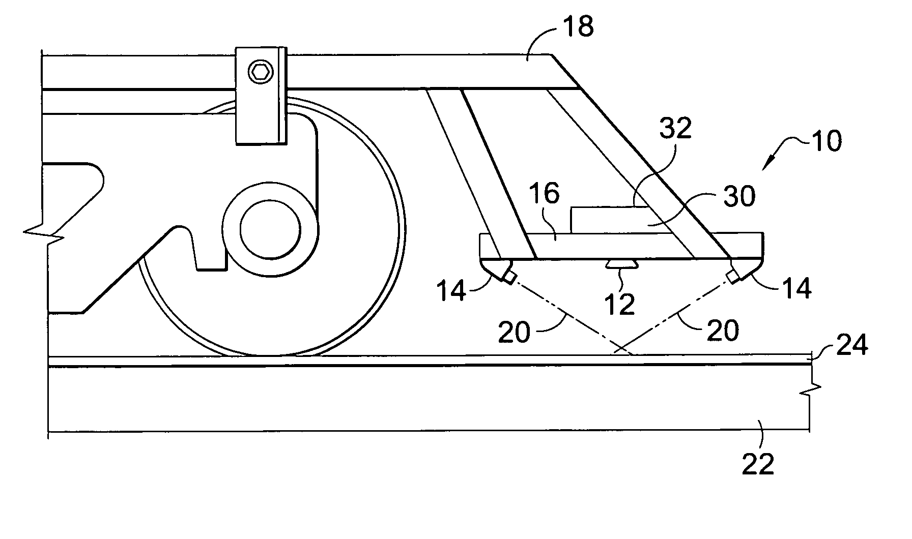
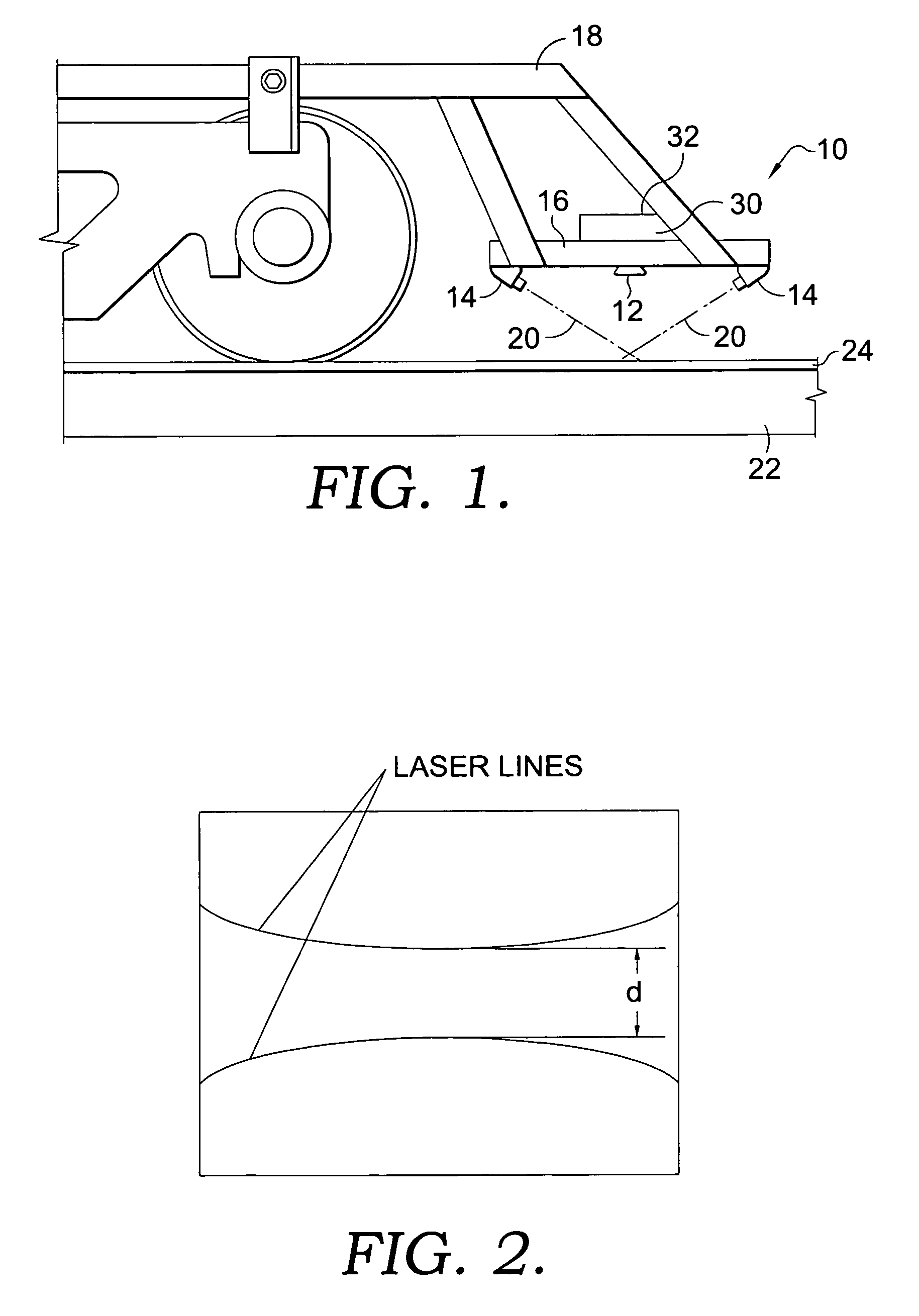
[0043]FIG. 1 illustrates the on-board, noncontact measurement system 10 of the present invention. The system 10 measures vertical track displacement relative to the wheel-and-rail contact point and these relative measurements are combined with an analytical model of the track structure and the measured vehicle loads (weight and dynamic forces) to estimate the vertical track modulus and track stiffness for the track. Vertical track stiffness is the ratio of applied load to displacement and includes the effects from rail, subgrade, ballast, subballast, ties, and fasteners. Vertical track modulus generally does not include the effects of the rail.

[0044]The system 10 comprises a digital vision system 12, a means for measuring the vertical distance between a position on the rail vehicle and the upper surface of the rail 14, and a data processor (not shown). The digital vision system is preferably a digital video camera having a storage device for recording the images. As shown in FIG. 1,...


PUM


Abstract

An on-board, noncontact measurement system and method is disclosed for measuring track quality, vertical track stiffness and vertical track modulus for a portion of track underlying the rail vehicle. The system comprises first and second optical emitters mounted to the vehicle and configured to emit beams of light that are detectable on the underlying surface; a camera mounted to the vehicle for recording the distance between the beams of light as the vehicle travels along the surface, a mechanism for measuring the distance between the beams of light for a particular portion of the surface; and a mechanism for determining the vertical track stiffness or vertical track modulus for a particular portion of the track.

Description

CROSS-REFERENCE TO RELATED APPLICATIONS[0001]This application claims priority to commonly owned U.S. provisional application Ser. No. 60 / 625,514, filed Nov. 5, 2004, is incorporated by reference in their entirety.TECHNICAL FIELD[0002]The invention relates generally to methods and apparatus for surface modulus measurement and, more particularly, to methods and apparatus for noncontact, onboard, vertical track modulus measurement.BACKGROUND OF THE INVENTION[0003]Track quality is a major factor in railroad safety. One accepted indicator of track quality is the rail's vertical track modulus. Track modulus is defined as the coefficient of proportionality between the vertical rail deflection and the vertical contact pressure between the rail base and track foundation; it can be re-stated as the supporting force per unit length of rail, per unit rail deflection.[0004]Railway track has several components that all contribute to track stiffness including the rail, subgrade, ballast, subballas...

Claims


Application Information

Patent Timeline
Patent Type & Authority Patents(United States)
IPC IPC(8): G01B11/14
CPCG01N3/48B61K9/08
Inventor FARRITOR, SHANEARNOLD, RICHARDNORMAN, CHRIS
Owner BOARD OF RGT UNIV OF NEBRASKA
Why Eureka
Try Eureka