System and methods of performing real-time on-board automotive telemetry analysis and reporting

a real-time, automotive technology, applied in the field of automotive test systems, can solve the problems of increasing complexity of the on-board vehicle sensor network, and achieve the effects of easy movement, convenient and safe operation, and extended capability of the expert system

Inactive Publication Date: 2006-10-12
HUDSON MICHAEL D +1
View PDF31 Cites 273 Cited by
  • Summary
  • Abstract
  • Description
  • Claims
  • Application Information

AI Technical Summary

Benefits of technology

[0019] An advantage of the present invention is that the diagnostic controller is capable of analyzing, in real-time, sensor data received in all operating modes of the vehicle, including in particular during in-service use. Additionally the diagnostic controller is able to schedule and perform diagnostic tests at appropriate times in the operation of the vehicle, again including in particular during in-service use. Sensor data analysis performed during in-service use of the vehicle allows detection of even subtle and intermittent operation variances potentially predictive of impending component faults. In-service selection and execution of condition dependent diagnostic tests further aids in the identification of potential component faults through controlled perturbation of operational conditions specifically chosen to test for potentially identified faults. Testing under in-service conditions which cannot be simulated in service-bay contexts, is readily and safely performed by the diagnostic controller of the present invention.
[0020] Another advantage of the present invention is that the diagnostic controller implements a rules-ba...

Problems solved by technology

The most common conventional analyzers are fixed units or mounted on service carts with limited mobility.
Manually initiated overrides enable limited simulation of operating conditions not otherwise achievable in the stationary, idle operation of a vehicl...

Method used


Image

  • System and methods of performing real-time on-board automotive telemetry analysis and reporting
  • System and methods of performing real-time on-board automotive telemetry analysis and reporting
  • System and methods of performing real-time on-board automotive telemetry analysis and reporting

Examples


Embodiment Construction

[0029] Along with the increasing complexity of embedded computer-based automobile control systems, and vehicular control systems in general, there is an increasing demand for improved monitoring and control of these systems generally for the purpose of optimizing performance and minimizing the costs of maintenance. The present invention is directed at providing an efficient, effective diagnostic system capable of monitoring performance and predictively identifying potential as well as actual failures of vehicle system components. For ease of use, the diagnostic system of the present invention is capable of autonomous operation in general and specifically in selection of vehicle system tests to actively identify potential vehicle operating problems. In the following detailed description of the invention like reference numerals are used to designate like parts depicted in one ore more of the figures.

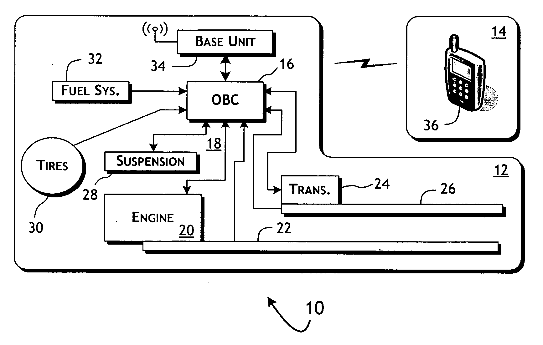
[0030]FIG. 1 provides a representation of a conventional automotive system 10 further...


PUM


Abstract

Active diagnosis of current operating and potential fault conditions in the operation of the vehicle is implemented using a diagnostic controller interoperating with an on-board vehicle control system as installed within a vehicle. The diagnostic controller supports autonomous execution of diagnostic tests initiated dependent on the operational state of the vehicle. The control system includes a diagnostics control manager that autonomously selects test routines for execution at defined operational states, including in-service operational states, a monitor, responsive to sensor data retrieved in real-time from the on-board vehicle control system, operative to detect a current instance of the in-service operational state of the vehicle, and a diagnostic test scheduler operative to initiate execution of the diagnostic test routine upon detection of the current instance of the in-service operational state of the vehicle.

Description

[0001] This application claims the benefit of U.S. Provisional Application No. 60 / 670,450, filed Apr. 12, 2005.BACKGROUND OF THE INVENTION [0002] 1. Field of the Invention [0003] The present invention is generally related to automotive test systems and, in particular, to a wireless telemetry-based system enabling real-time diagnostics of automotive systems. [0004] 2. Description of the Related Art [0005] Vehicles, including automobiles in particular, have implemented relatively sophisticated on-board data collection and diagnostic systems for a considerable number of years. Typically implemented as embedded processor systems, these electronic control units (ECUs), often generically referred to as on-board controllers, are used to monitor and control engine, exhaust and other operating vehicle functions. The monitoring and control operations are enabled by a network of sensors and actuators distributed at appropriate control points throughout the vehicle. The electronic control unit ...

Claims


Application Information

Patent Timeline
IPC IPC(8): G01M17/00
CPCG01M15/05G06F11/0739G05B23/021G07C5/085G07C5/008
Inventor HUDSON, MICHAEL D.MCARTHUR, KELLY M.
Owner HUDSON MICHAEL D
Why Eureka
Try Eureka