
Computer case with optical disk drive mounted on chassis front

a computer case and chassis technology, applied in the direction of instruments, static indicating devices, electric apparatus casings/cabinets/drawers, etc., can solve the problems of inconvenient computer handling, reduced space portion increased whole volume of the computer case, etc., to facilitate the use of optical disk drives and reduce front and rear widths

Inactive Publication Date: 2008-07-22
GM CORP LTD
View PDF2 Cites 0 Cited by
  • Summary
  • Abstract
  • Description
  • Claims
  • Application Information

AI Technical Summary

Benefits of technology

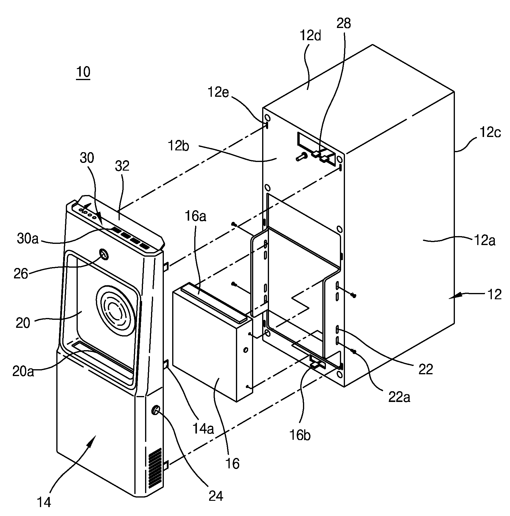
"The present invention provides a computer case with an optical disk drive mounted on the front of the case. This design reduces the width of the computer case and makes it easier to use the optical disk drive. The computer case has a unique design that improves the image of the product. The case includes a receiving portion for inserting and placing the optical disk drive, a tray moving groove for inserting and drawing out a disk tray, and a fixing piece for fixing the optical disk drive. The chassis front also has a disk drive operation switch and a main switch for controlling the operation of the computer. The function portion section on the chassis front includes a plurality of function ports and is opened and closed by a cover."

Problems solved by technology

However, since a conventional computer case in which the computer main body is placed has a structure in which the optical disk drives such as CDP, DVDP and the like are inserted and mounted from the front plate of the computer case to the inside of the space portion, the volume of the space portion in the computer case is decreased and thereby the whole volume of the computer case is unavoidably increased to ensure the volume of the space portion in the computer case.
Meanwhile, in the case where the volume of the computer case is increased, it causes problems in that it is very inconvenient to handle the computer and it occupies a large space to reduce the space utilization.
Accordingly, the operation of loading the disk on the disk tray in a sitting posture is very inconvenient and, further, if the disk is not properly loaded on the disk tray, a malfunction occurs.

Method used


Image

  • Computer case with optical disk drive mounted on chassis front
  • Computer case with optical disk drive mounted on chassis front
  • Computer case with optical disk drive mounted on chassis front

Examples


Embodiment Construction

[0022]Hereinafter, preferred embodiments in accordance with the present invention will be described with reference to the accompanying drawings. The preferred embodiments are provided so that those skilled in the art can sufficiently understand the present invention, but can be modified in various forms and the scope of the present invention is not limited to the preferred embodiments.

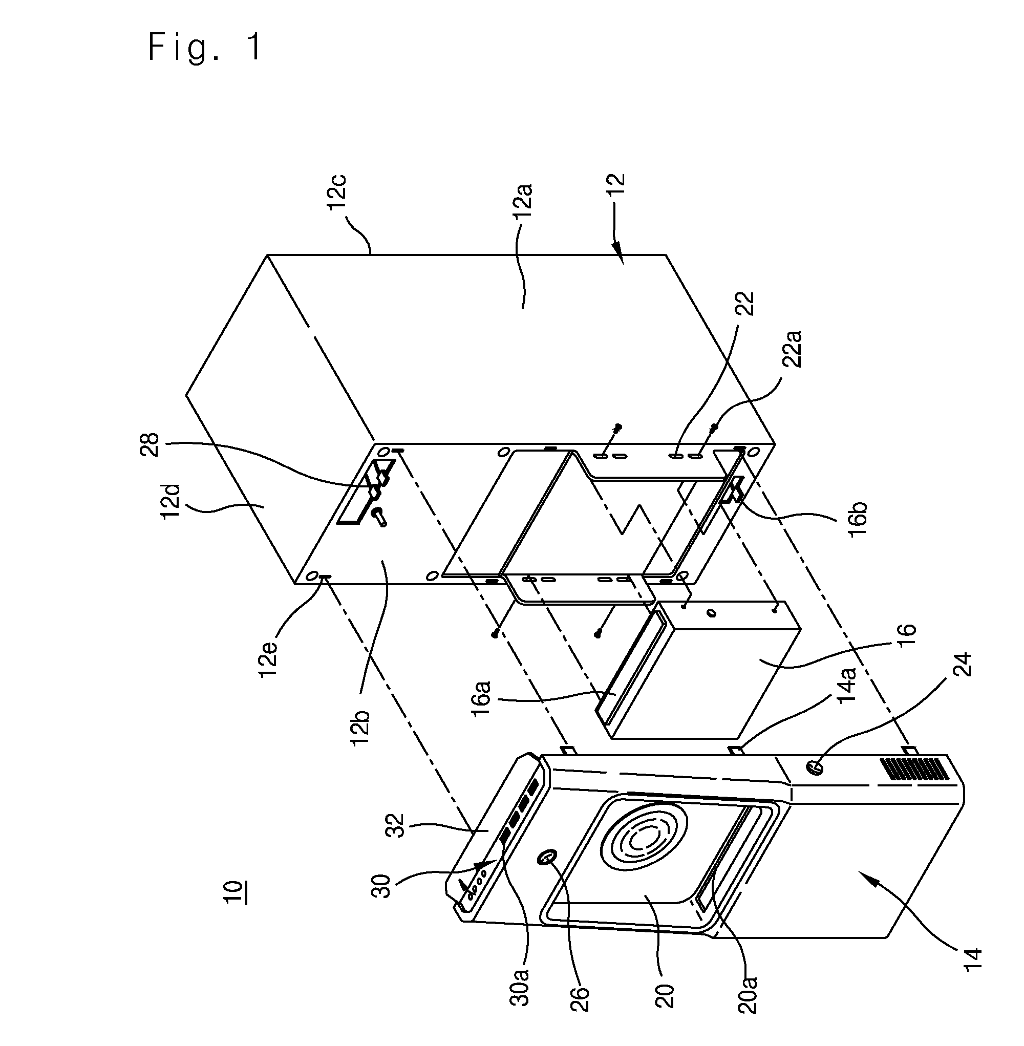
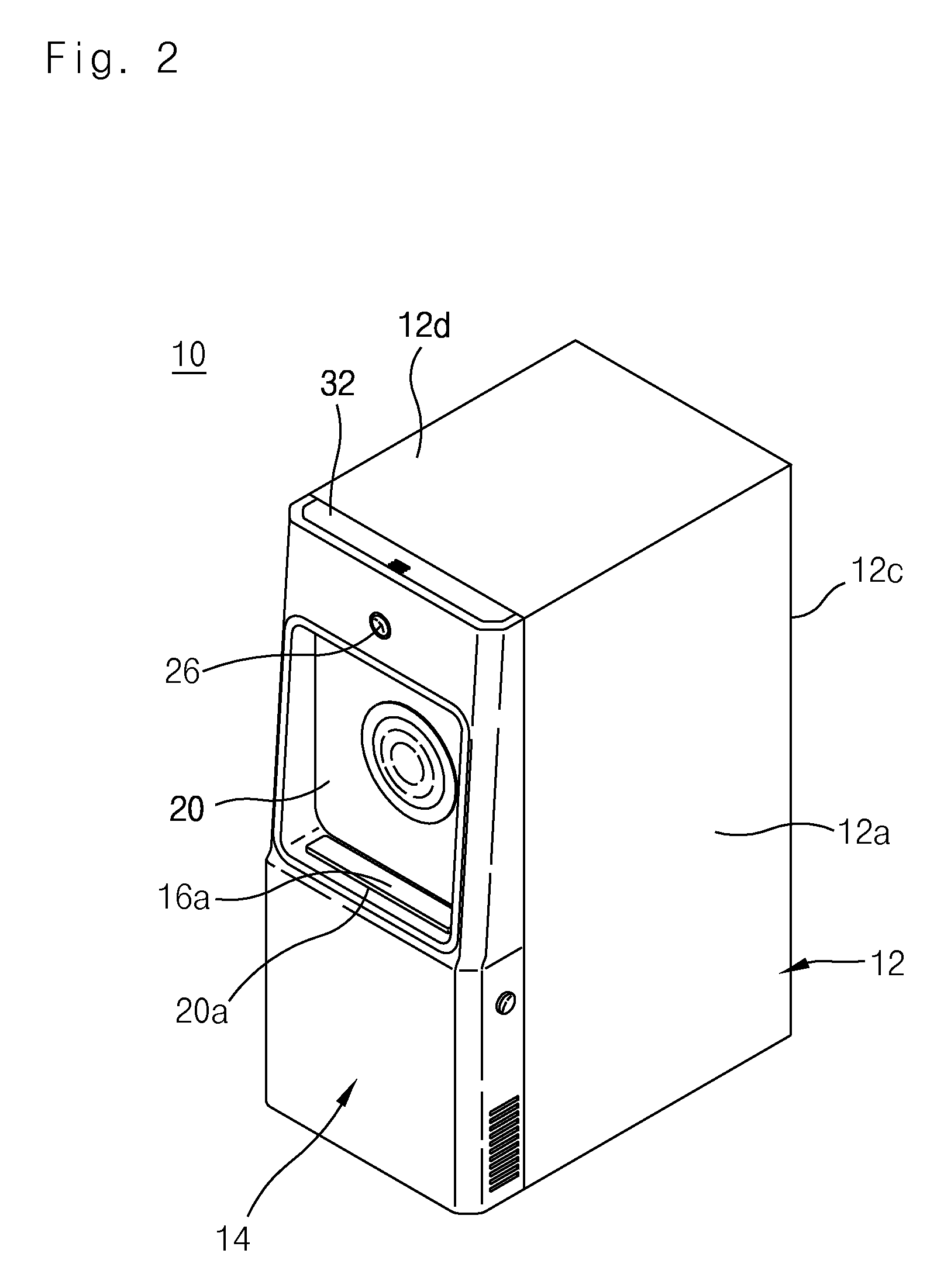
[0023]FIG. 1 a partially exploded perspective view depicting a computer case in which an optical disk drive is mounted on a chassis front in accordance with the present invention, and FIG. 2 is a perspective view depicting a connection state of FIG. 1.

[0024]FIG. 3 is a side cross-sectional view of a chassis front that constitutes a computer case in accordance with the present invention.

[0025]Moreover, FIG. 4 is a perspective view depicting a state where a disk tray of an optical disk drive is drawn out in a tray moving groove in an initial stage of operation in a computer case in which the optical disk...


PUM


Abstract

Disclosed herein is a newly-designed computer case with an optical disk drive mounted on a chassis front, in which an optical disk drive such as a compact disk player (CDP), a digital video disk player (DVDP) and the like is mounted on a chassis front the computer case so as to reduce the front and rear width of the computer case to a size corresponding to the front and rear length of the optical disk drive, to facilitate the use of the optical disk drive, and to improve the image of the product with a unique design.

Description

CROSS-REFERENCE TO RELATED APPLICATION[0001]This application claims the benefit of Korean Patent Application Nos. 10-2006-0114349, filed on Nov. 20, 2006 and 10-2007-0001895, filed on Jan. 8, 2007, the entire disclosures of which are hereby incorporated by reference.BACKGROUND OF THE INVENTION[0002]1. Field of the Invention[0003]The present invention relates to a computer case with an optical disk drive mounted on a chassis front and, more particularly, to a computer case in which an optical disk drive such as a compact disk player (CDP), a digital video disk player (DVDP) and the like is mounted on a chassis front that constitutes the computer case so as to reduce the front and rear width of the computer case by a size corresponding to the front and rear length of the optical disk drive, to facilitate the use of the optical disk drive, and to improve the image of the product with a unique design.[0004]2. Description of Related Art[0005]Recently, as computers have been mainly used i...

Claims


Application Information

Patent Timeline
Patent Type & Authority Patents(United States)
IPC IPC(8): G06F1/16
CPCG06F1/181
Inventor KIM, MUN CHUL
Owner GM CORP LTD
Learn More