Dialyzer capping machine

A dialyzer and capping machine technology, applied in metal processing equipment, metal processing, manufacturing tools, etc., can solve the problems of product performance defects, low production efficiency, and high labor costs

Active Publication Date: 2021-09-10
明基生物技术上海有限公司
View PDF11 Cites 0 Cited by
  • Summary
  • Abstract
  • Description
  • Claims
  • Application Information

AI Technical Summary

Problems solved by technology

Most of the existing blood cap filling steps are semi-automatic assembly, which not only has high labor costs and low production efficiency, but also has the risk of improper installation by manual operation, which may easily cause performance defects of the final product

Method used


Image

  • Dialyzer capping machine
  • Dialyzer capping machine
  • Dialyzer capping machine

Examples


Embodiment 1

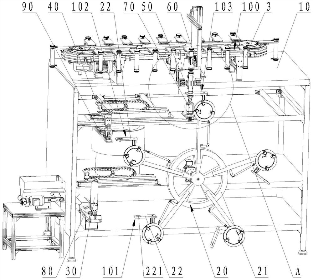
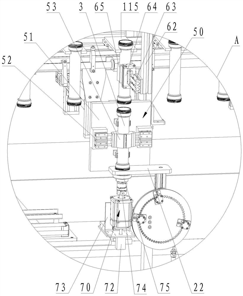
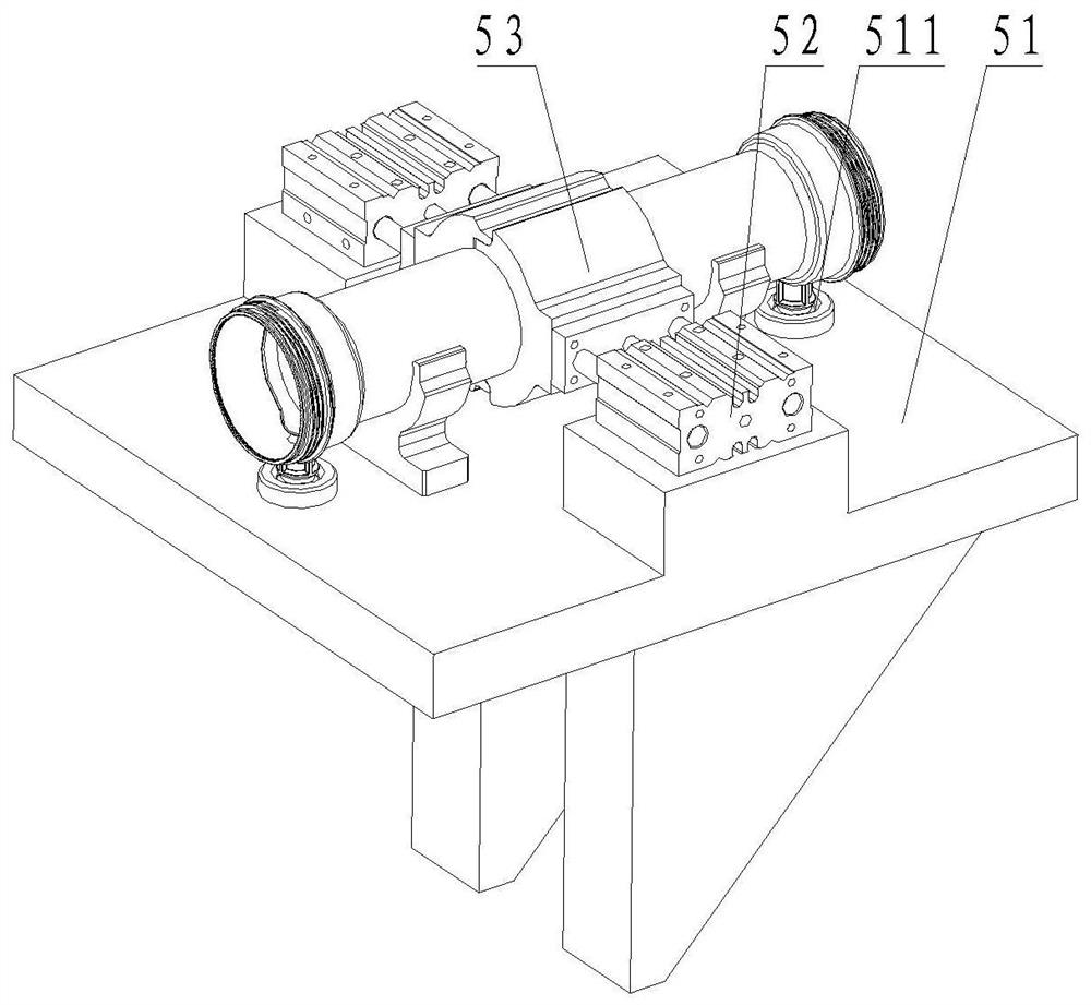
[0076] A dialyzer capping machine, such as figure 1 As shown, it includes a frame 10 , a rotating mechanism 20 , a blood cap grabbing mechanism 30 , a sealing ring grabbing mechanism 40 , a semi-finished product clamping mechanism 50 , a semi-finished product grabbing mechanism 60 and a blood cap tightening mechanism 70 . The frame 10 is provided with a blood cap upper station 101 , an upper sealing ring station 102 and a blood cap tightening station 103 sequentially from bottom to top along the height direction.

[0077] Such as figure 1 As shown, the rotating mechanism 20 includes a turntable 21 and a plurality of stages 22, the turntable 21 is arranged on the frame 10 and is rotatably arranged in the height direction of the frame 10, and a plurality of stages 22 are arranged on the turntable 21 at intervals, The stage 22 is provided with a loading hole 221 , and the upper blood cap station 101 , the upper sealing ring station 102 and the blood cap tightening station 103 ar...

Embodiment 2

[0091] On the basis of the first embodiment above, as figure 1 As shown, the dialyzer capping machine also includes a blood cap delivery mechanism 80 , a sealing ring delivery mechanism 90 and a semi-finished product delivery mechanism 100 . The blood cap conveying mechanism 80 is arranged on the frame 10 and the output end of the blood cap conveying mechanism 80 is located below the blood cap grasping mechanism 30 , and the blood cap conveying mechanism 80 is used for conveying the blood cap.

[0092] The sealing ring conveying mechanism 90 is arranged on the frame 10 and the output end of the sealing ring conveying mechanism 90 is located below the sealing ring grasping mechanism 40 , and the sealing ring conveying mechanism 90 is used for conveying the sealing ring.

[0093] The semi-finished product conveying mechanism 100 is arranged on the frame 10 and located above the semi-finished product clamping mechanism 50, and the semi-finished product conveying mechanism 100 is ...

Embodiment 3

[0115] On the basis of the above-mentioned embodiment one or embodiment two, as Figure 17 and Figure 18 As shown, the rotating mechanism 20 also includes a plurality of angle adjustment components, and the stage 22 is connected with the turntable 21 through the angle adjustment components. The angle adjustment assembly includes a first connecting piece 23, a second connecting piece 24 and a fifth telescopic cylinder 25. One end of the first connecting piece 23 is connected to the turntable 21, and the other end of the first connecting piece 23 is connected to one end of the second connecting piece 24. Hinged, the object table 22 is arranged on the other end of the second connector 24, the telescopic end of the fifth telescopic cylinder 25 is hinged with the second connector 24, and the other end of the fifth telescopic cylinder 25 is hinged with the first connector 23; When the telescopic cylinder 25 stretches, the angle between the first connector 23 and the second connect...


PUM


Abstract

The invention belongs to the field of dialyzer equipment, and discloses a dialyzer capping machine which comprises a rack, a rotating mechanism, a blood cover grabbing mechanism, a sealing ring grabbing mechanism, a semi-finished product clamping mechanism, a semi-finished product grabbing mechanism and a blood cover tightening mechanism, wherein the rack is provided with a blood cover feeding station, a sealing ring feeding station and a blood cover tightening station; the rotating mechanism comprises a rotating disc and a plurality of objective tables, and the multiple objective tables are arranged on the rotating disc at intervals; and the blood cover feeding station, the sealing ring feeding station and the blood cover tightening station are located on rotating tracks of the objective tables. According to the dialyzer capping machine, a blood cover is grabbed onto the objective table of the blood cover feeding station through the blood cover grabbing mechanism, and a sealing ring is grabbed into the blood covers through the sealing ring grabbing mechanism; a semi-finished product is placed in the semi-finished product clamping mechanism through the semi-finished product grabbing mechanism, and automatic tightening and mounting of the blood cover are achieved through the semi-finished product clamping mechanism and the blood cover tightening mechanism; not only is the labor cost reduced and the assembly efficiency is improved, but also the risk that installation is not in place due to manual operation is reduced; and the product quality is stable.

Description

technical field [0001] The invention relates to the field of dialyzer equipment, in particular to a dialyzer capping machine. Background technique [0002] Hemodialysis is also known as artificial kidney, commonly known as kidney dialysis or kidney dialysis. It mainly treats acute and chronic renal failure. It is one of the artificial kidney replacement treatments, and it is also the main and most effective treatment. The main purpose of treatment is to eliminate metabolic waste in the patient's blood, remove toxins and excess water in the patient's body, and maintain the water, electrolyte and acid-base balance in the patient's body. [0003] The hemodialyzer is the most core device in hemodialysis. The dialyzer is in contact with blood and performs hemodialysis. Its performance directly affects the treatment effect of patients. Hemodialyzer, dialysis equipment, pipelines, etc. together constitute hemodialysis treatment. [0004] The hemodialyzer is mainly composed of ho...

Claims


Application Information

Patent Timeline
IPC IPC(8): B23P19/04
CPCB23P19/04
Inventor 何红星葛俊麟樊诗海
Owner 明基生物技术上海有限公司
Why Eureka
Try Eureka