Vacuum traction device

a vacuum traction and traction device technology, applied in the direction of air-cushion, vehicle components, vehicles, etc., can solve the problems of increased difficulty, difficulty, inconvenience,

Inactive Publication Date: 2008-07-29
MOBILE ROBOT INTEGRATION
View PDF5 Cites 15 Cited by
  • Summary
  • Abstract
  • Description
  • Claims
  • Application Information

AI Technical Summary

Problems solved by technology

These surfaces can be inconvenient, difficult or even dangerous, for people to access directly.
The difficulty can be increased when these surfaces are curved, compound, or tapered.

Method used


Image

  • Vacuum traction device
  • Vacuum traction device
  • Vacuum traction device

Examples


Embodiment Construction

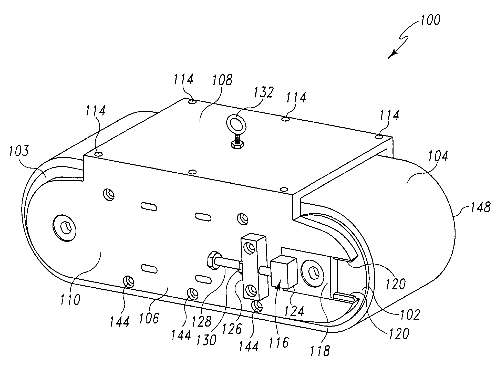
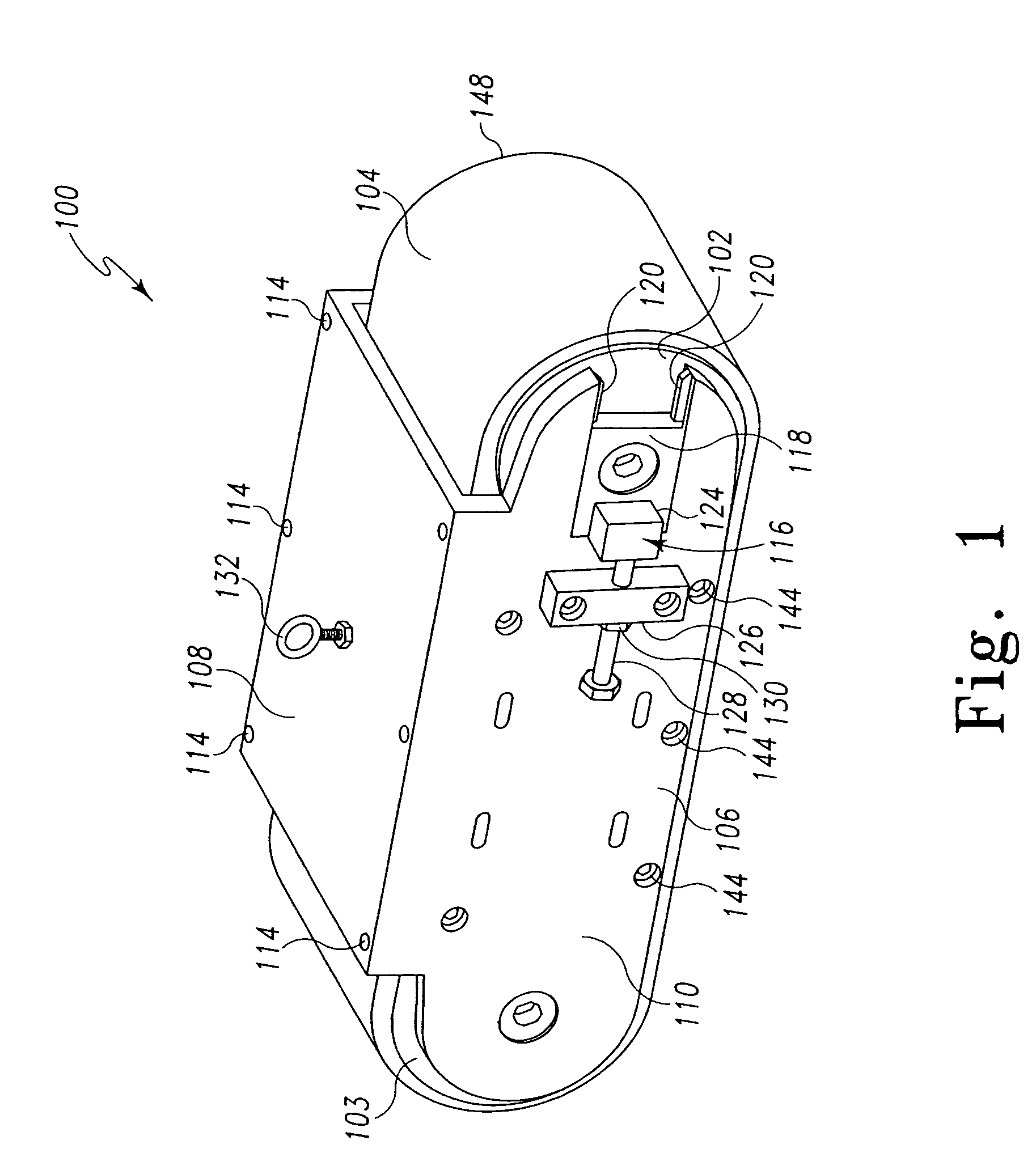
[0020]A traction device 100 is shown in FIG. 1. As will be discussed in more detail, this traction device 100 is useful for clinging to and maneuvering on inclined, inverted, and vertical surfaces that are difficult to access directly. The traction device 100 includes a first roller 102 and a second roller 103 that support a continuous traction belt 104. The rollers 102 and 103 are mounted on a frame 106. In the embodiment of FIGS. 1-3, the frame 106 includes top plate 108 and side plate 110. Support braces 112 are provided internally to help reinforce frame 106. The frame 106 serves as a support and scaffold for the rollers 102 and 103, and additional components of the traction device 100. Bolts 114 are used to securely fasten the top plate 108 to the side plates 110, and to fasten the braces 112 to the side plates 110. The exact configuration and components used for the frame 106 are not crucial.

[0021]A tensioning mechanism 116 is provided in association with the first roller 102....


PUM


Abstract

A traction device includes a continuous traction belt provided on a pair of opposing rollers. The traction belt includes openings such that a vacuum may be applied through the traction belt causing the traction device to cling to a working surface. A motor may be provided to drive one of the rollers and thereby drive the belt. A plurality of such traction devices may be coupled with a control mechanism to form a robot. A system is described for performing work or maintenance on a structure having an inclined working surface that includes a support robot for positioning at a high point on the structure and a payload robot attached to the support robot by an umbilical or tension cord for maneuvering along the working surface.

Description

FIELD OF INVENTION[0001]This invention relates to traction devices for adhering and moving tools across vertical, inverted, inclined, curved, compound, and tapered surfaces.BACKGROUND OF THE INVENTION[0002]It is often desirable to hold a tool in close proximity to a vertical, inverted, inclined surface, curved, compound, or tapered surface and to move the tool to various locations on the surface. Some common scenarios include inspecting, cleaning, depainting, or otherwise maintaining the surfaces of airplanes, submarines, storage tanks, high rise buildings, and other similar structures. These surfaces can be inconvenient, difficult or even dangerous, for people to access directly. The difficulty can be increased when these surfaces are curved, compound, or tapered. Accordingly, it has been known to use an apparatus capable of traversing such surfaces and for supporting tools to work on the surfaces. For example, Jeswine, U.S. Pat. No. 6,742,617, discloses a surface clinging unit tha...

Claims


Application Information

Patent Timeline
Patent Type & Authority Patents(United States)
IPC IPC(8): B60B39/00
CPCB62D55/265
Inventor IMUS, RICHARD L.IMUS, MARC S.MITTMANN, PAUL A.MITTMANN, JOHN L.
Owner MOBILE ROBOT INTEGRATION
Why Eureka
Try Eureka