
Image generating device, image generating method, and image generating program

Inactive Publication Date: 2008-08-05
SEIKO EPSON CORP
View PDF11 Cites 10 Cited by
  • Summary
  • Abstract
  • Description
  • Claims
  • Application Information

AI Technical Summary

Benefits of technology

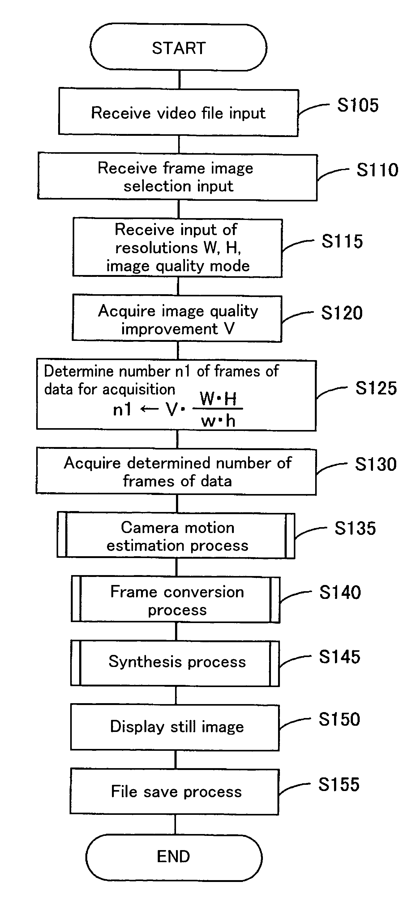
[0011]With the foregoing in view, it is an object of the present invention provide a technique capable of efficiently executing a process for generating image data that represents a still image, in order to efficiently produce a still image.

Problems solved by technology

The former technique has the drawback of requiring extended processing time, due to generation of more image data than is necessary for the required image quality, resulting from the fixed number of frames of data synthesized.
The latter technique has the drawback also has the drawback of requiring extended processing time, since frame information continues to be synthesized until determination is made that a scene change has occurred or that input of frame information has been completed, thus also generating more image data than necessary for the required image quality.

Method used


Image

  • Image generating device, image generating method, and image generating program
  • Image generating device, image generating method, and image generating program
  • Image generating device, image generating method, and image generating program

Examples


embodiment 2

(6) Embodiment 2

[0199]In the synthesis process shown in FIG. 17, since the distance MinL(i, f) to the shortest pixel is calculated, the number of frames of data may be determined using this distance.

[0200]FIG. 21 is a flowchart depicting a process performed by the image generating device pertaining to a second embodiment. In this embodiment, processes S505-520 and S540-S550 are performed by frame acquiring module.

[0201]While not shown in the drawing, after input specifying a file name has been received, and a frame image at a certain location where it is desired to generate a still image has been selected, as in S105-S100 of FIG. 11, vertical / horizontal resolution and image quality mode setting inputs are received, and horizontal resolution W, vertical resolution H, and a image quality setting value are acquired (S505). Next, referring the correspondence table shown in FIG. 6, a threshold value TH1 corresponding to the image quality setting value (image quality setting data) is acqu...

embodiment 3

(7) Embodiment 3

[0207]FIG. 22 is a flowchart depicting the process performed by the image generating device pertaining to a third embodiment; and FIG. 23 illustrates by means of a flowchart the synthesis process (2) carried out in S635. First, synthesis process (2) will be described.

[0208]First, a threshold value Lth for shortest pixel distance is acquired (S705). For example, a print interface screen having a predetermined selection field may be displayed, and a parameter indicating threshold value Lth acquired from input into the selection field, and stored in RAM.

[0209]Here, as shown in FIG. 24, the threshold value Lth for shortest pixel distance is a threshold value for determining whether a pixel of frame data is within a predetermined distance from a pixel of interest i. In the illustrated example, threshold value Lth is set to ½ the distance between pixels in the image data being generated. The circles represented by dotted lines centered on pixels, including a pixel of inter...

embodiment 4

(8) Embodiment 4

[0226]FIG. 25 is a flowchart depicting the process performed by the image generating device pertaining to a fourth embodiment; and FIG. 26 illustrates by means of a flowchart the synthesis process (3) carried out in S835. First, synthesis process (3) will be described.

[0227]First, a “0” is placed in a counter nu provided in RAM (S905). Next, in the same manner as in S505-S520 of FIG. 23, threshold value Lth for shortest pixel distance is acquired; a location of a pixel of interest i for generating image data for tone representation of a still image is established, from among all pixels of all frames of data; distances {(xf−x0)2+(yf−y0)2}1 / 2 between pixels at coordinates (xf, yf) neighboring the pixel of interest i, and the pixel of interest i at coordinates (x0, y0) are calculated; and pixels of frames of data for which calculated distance is equal to or less than the threshold value Lth are selected (S910-S925).

[0228]Next, a determination is made as to whether the n...


PUM


Abstract

Designed to determine a number of frames of data for acquisition from video data on the basis of image quality setting data that allows image quality to be set for an image output by an image output device; and to acquire from the video data the determined number of frames of data, and synthesize the acquired number of frames of data to generate image data representing tones of an image by means of a multitude of pixels. Since image data can be generated by synthesizing frames of data in a number appropriate to the image quality of the output image, the process of generating image data representing a still image can be performed efficiently, and a still image derived efficiently.

Description

CROSS-REFERENCE TO RELATED APPLICATION[0001]This application claims priority under 35 U.S.C. § 119 based on Japanese Application No. 2003-015171, filed on Jan. 23, 2003.BACKGROUND OF THE INVENTION[0002]1. Field of the Invention[0003]The present invention relates to a technique of generating image data from information consisting of multiple frames.[0004]2. Description of the Related Art[0005]Generation of image data representing a still image from video data representing video shot with a digital video camera or the like, and printing out of still images based on such image data, is known in the prior art. Video data is composed of data for a plurality of frames representing images by means of tone data for a multitude of pixels, on a pixel by pixel basis; image data that represents a still image by means of tone representation with a multitude of pixels is created by acquiring and synthesizing data for a predetermined number of frames selected from the video data.[0006]Since video ...

Claims


Application Information

Patent Timeline
IPC IPC(8): G06K9/36G06K9/32G06K9/40G06T3/00G06T3/40G06T5/00G06T7/20H04N1/387H04N5/91
CPCG06T3/40G06T5/003G06T2207/10016G06T5/73
Inventor AISO, SEIJI
Owner SEIKO EPSON CORP
Learn More