Method and apparatus for detecting rub in a turbomachine

a turbomachine and rub detection technology, applied in the direction of positive displacement liquid engines, instruments, nuclear elements, etc., can solve the problems of turbomachine blades and seals being damaged, impact between stator blade tips and rotor seals, and impact between the seals on the shell and the rotating blade tips being affected,

Active Publication Date: 2008-08-05
GENERAL ELECTRIC CO
View PDF10 Cites 51 Cited by
  • Summary
  • Abstract
  • Description
  • Claims
  • Application Information

AI Technical Summary

Problems solved by technology

Consequently, if insufficient tip clearance is provided at assembly, impact between the stator blade tips and rotor seals and impact between the seals on the shell and the rotating blade tips may occur when certain operating conditions are reached.
These forces may also cause rubs.
Rubs may cause damage to the blades and seals of the turbomachine.
However, these systems are disadvantageous in that they require the use of very complicated and expensive vibration monitoring systems which are able to provide 1× and 2× amplitude, phase, polar and bode vibration data.
Another disadvantage of these systems is that a rub determination is usually made only after subsequent analysis of the data and not made in real time.

Method used


Image

  • Method and apparatus for detecting rub in a turbomachine
  • Method and apparatus for detecting rub in a turbomachine
  • Method and apparatus for detecting rub in a turbomachine

Examples


first embodiment

[0039]FIG. 10 shows a flow chart that represents the disclosed method which detects a possible rub event associated with abnormal eccentricity. At act 200 the on site monitor obtains data indicating vibration, eccentricity and load. At query 204 it is determined whether there has been abnormal vibration during a transient. A transient is when the turbomachine is going through startup or shut down and until breaker condition is ‘open’. At query 216 it is determined whether there has been abnormal vibration during a loaded state. At query 220 it is determined whether there is abnormal eccentricity while on turning gear. The turning gear consists of an electric motor connected to the turbomachine shaft and used to rotate the turbomachine shaft(s) and reduction gears at very low speeds. In an embodiment, abnormal eccentricity may be indicated when either (1) the eccentricity amplitude is above specified limits or (2) there is a larger than specified change in amplitude over a specified ...

second embodiment

[0040]FIG. 11 shows a flow chart that represents the disclosed method which detects a possible rub event associated with abnormal eccentricity. At act 248 the on site monitor obtains data indicating vibration, eccentricity and loading. At query 252 it is determined whether there has been abnormal vibration during a transient. If there has been abnormal vibration during transient, then an abnormal vibration during startup is indicated at act 256. At query 264 it is determined whether there has been abnormal vibration during a loaded state. At query 268 it is determined whether there is abnormal eccentricity while on turning gear. In an embodiment, abnormal eccentricity may be indicated when either (1) the eccentricity amplitude is above specified limits or (2) there is a larger than specified change in amplitude over a specified time period such as 10 seconds. If there is abnormal eccentricity while on turning gear, then at act 272 an abnormal eccentricity on turning gear is indicate...


PUM


Abstract

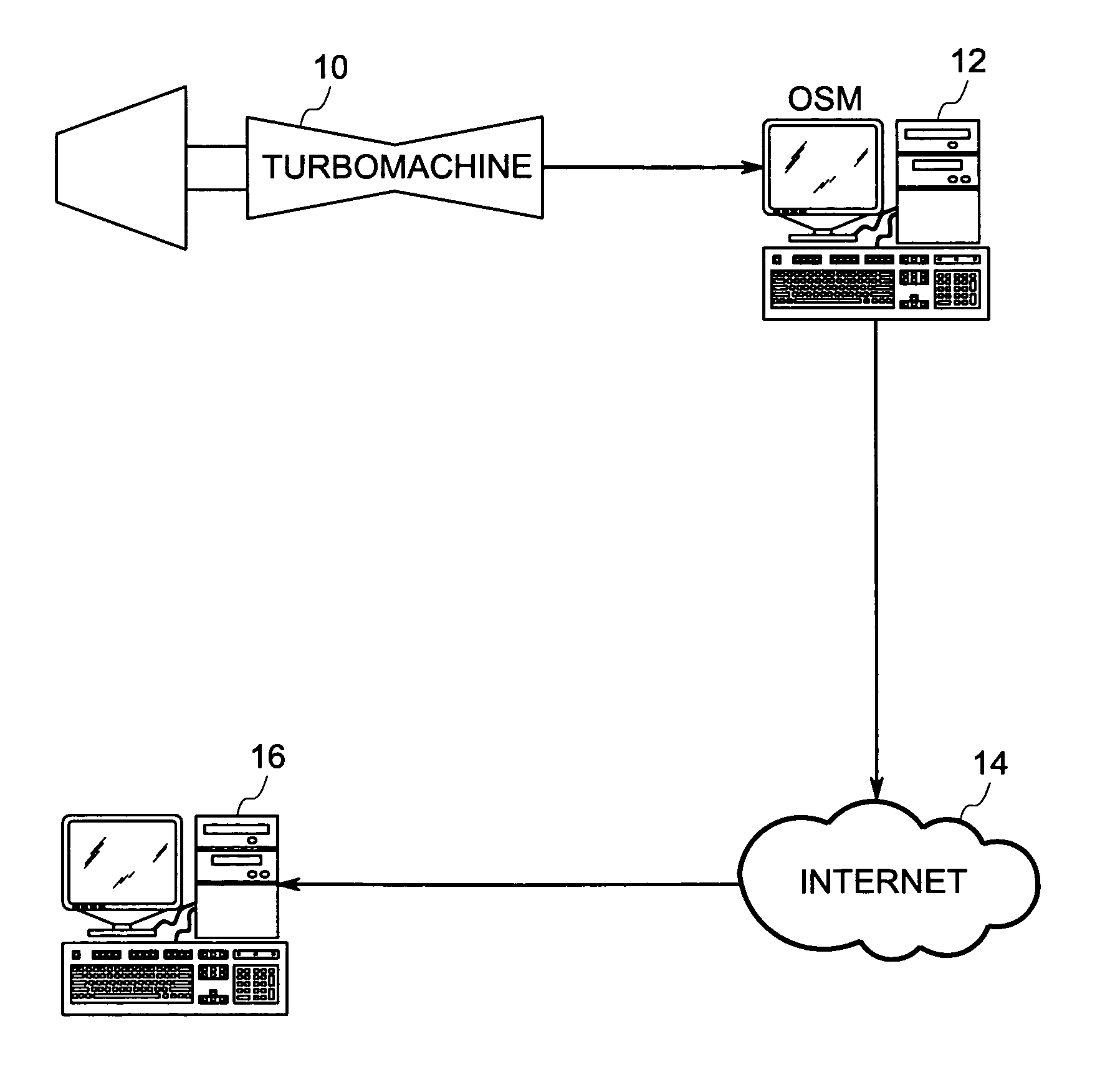
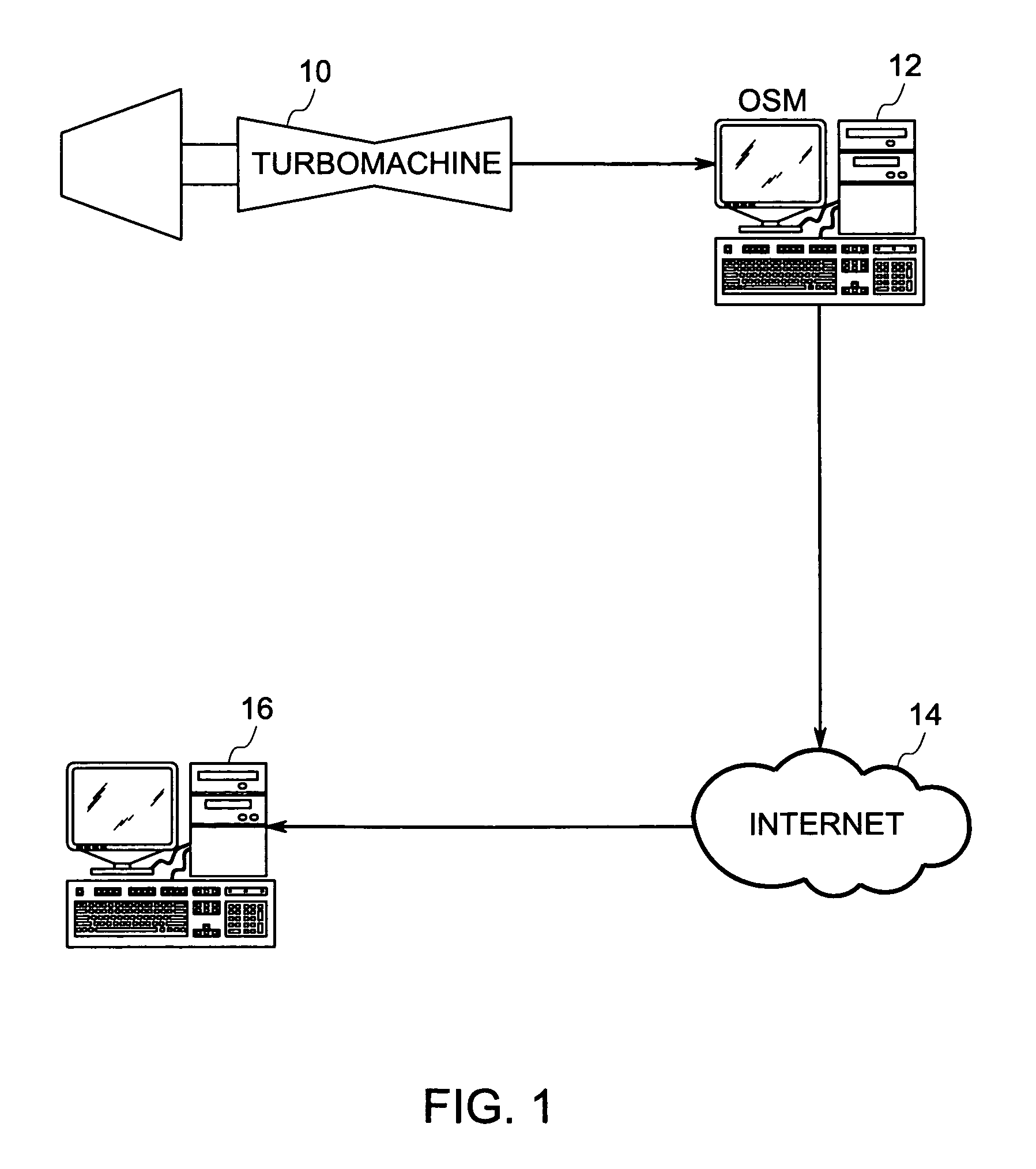
An embodiment of the disclosed method and apparatus relates to a system for detecting a rub in a turbomachine. The system includes a turbomachine; sensors monitoring turbomachine conditions; and an on site monitor in communication with the sensors, and loaded with instructions to implement a method for detecting a rub in the turbomachine.

Description

TECHNICAL FIELD[0001]The current disclosed method and apparatus relate to the monitoring and diagnosis of turbomachine rubs. More specifically, the disclosed method and apparatus relate to using algorithms which analyze data obtained from sensors monitoring various turbomachine operating conditions to determine when a rub event is occurring.BACKGROUND OF THE INVENTION[0002]Turbomachines generally have a centrally disposed rotor that rotates within a stationary cylinder or shell. The working fluid flows through one or more rows of circumferentially arranged rotating blades that extend radially from the periphery of the rotor shaft and one or more rows of circumferentially arranged stator blades that extend centripetally from the interior surface of the shell to the rotor shaft. The fluid imparts energy to the shaft that is used to drive a load, such as an electric generator or compressor. In order to ensure that as much energy as possible is extracted from the fluid, the tips of the ...

Claims


Application Information

Patent Timeline
Patent Type & Authority Patents(United States)
IPC IPC(8): G06F15/00F01D11/02F04D27/00F04B49/10G05B23/02
CPCF01D21/003F01D21/20F01D21/14F01D21/12
Inventor KANT, ABHAY SUDHAKARRAOBADAMI, VIVEK VENUGOPALTOTH, JOSEPH ROBERTGIANNAKOPOULOS, NICHOLASDIMOND, MARK M.KUMAR, JITENDRA
Owner GENERAL ELECTRIC CO
Why Eureka
Try Eureka