
Method and apparatus for performing test pattern autograding

a test pattern and autograding technology, applied in the direction of detecting faulty computer hardware, error detection/correction, instruments, etc., can solve the problems of large database, large hardware complexity, and inability of test engineers to devise test sequences manually (without computer assistance) to provoke desired behavior from the design

Inactive Publication Date: 2008-08-05
NORTH STAR INNOVATIONS
View PDF8 Cites 12 Cited by
  • Summary
  • Abstract
  • Description
  • Claims
  • Application Information

AI Technical Summary

Problems solved by technology

Moreover, the complexity of the hardware, in terms of the number of logic gates required, is immense, so that it usually impractical for a test engineer to devise test sequences manually (without computer assistance) to provoke desired behavior from the design under test.
Hence, these databases may become rather large.
Integrating test data from a number of such databases can be very difficult and, at best, highly inefficient.
Since a significant amount of post-processing is generally needed to determine the coverage of a given set of test sequences, relying on existing vendor tools can create a tremendous bottleneck in terms of both performance and storage requirements.

Method used


Image

  • Method and apparatus for performing test pattern autograding
  • Method and apparatus for performing test pattern autograding
  • Method and apparatus for performing test pattern autograding

Examples


Embodiment Construction

[0017]The following is intended to provide a detailed description of an example of the invention and should not be taken to be limiting of the invention itself. Rather, any number of variations may fall within the scope of the invention, which is defined in the claims following the description.

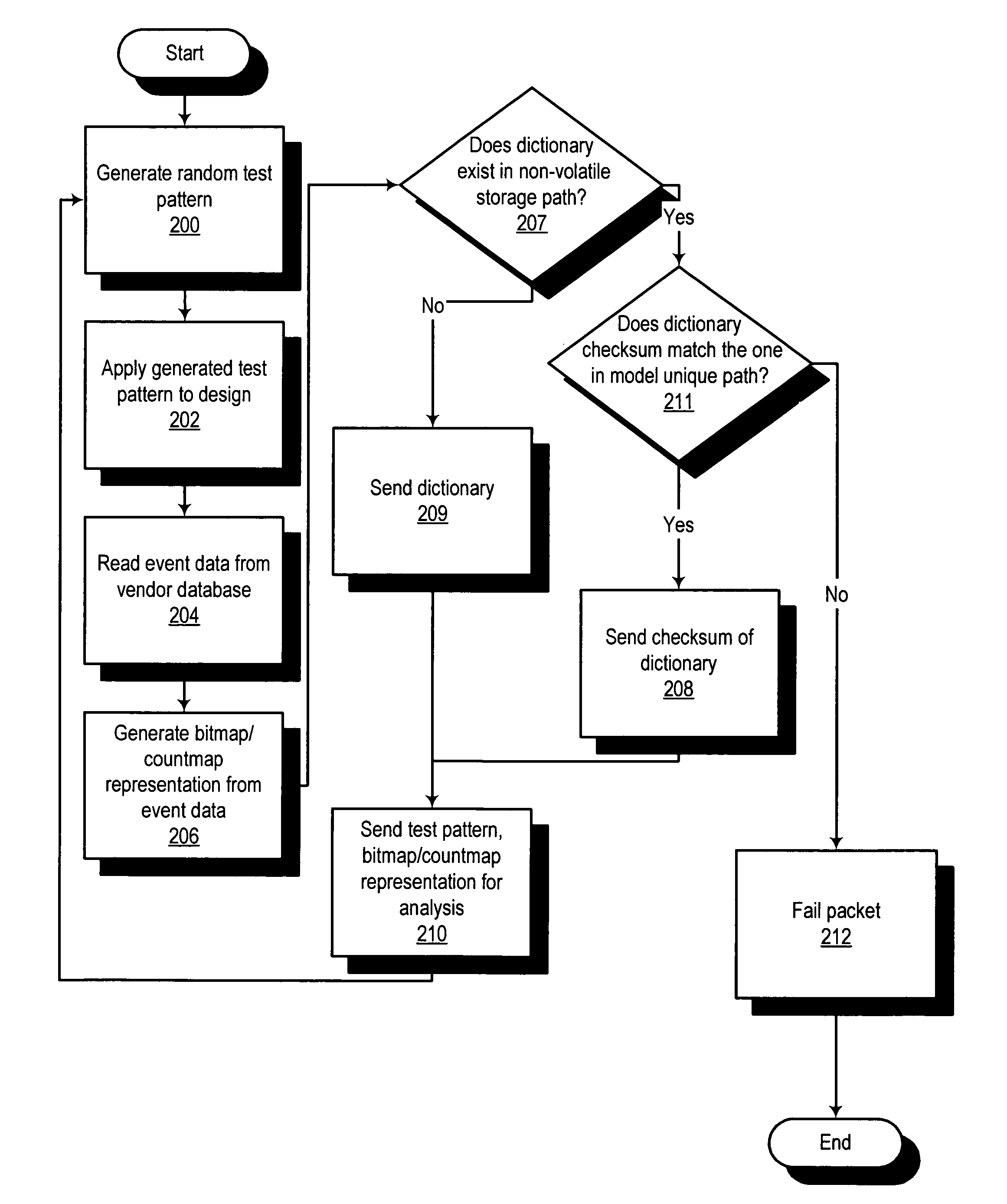
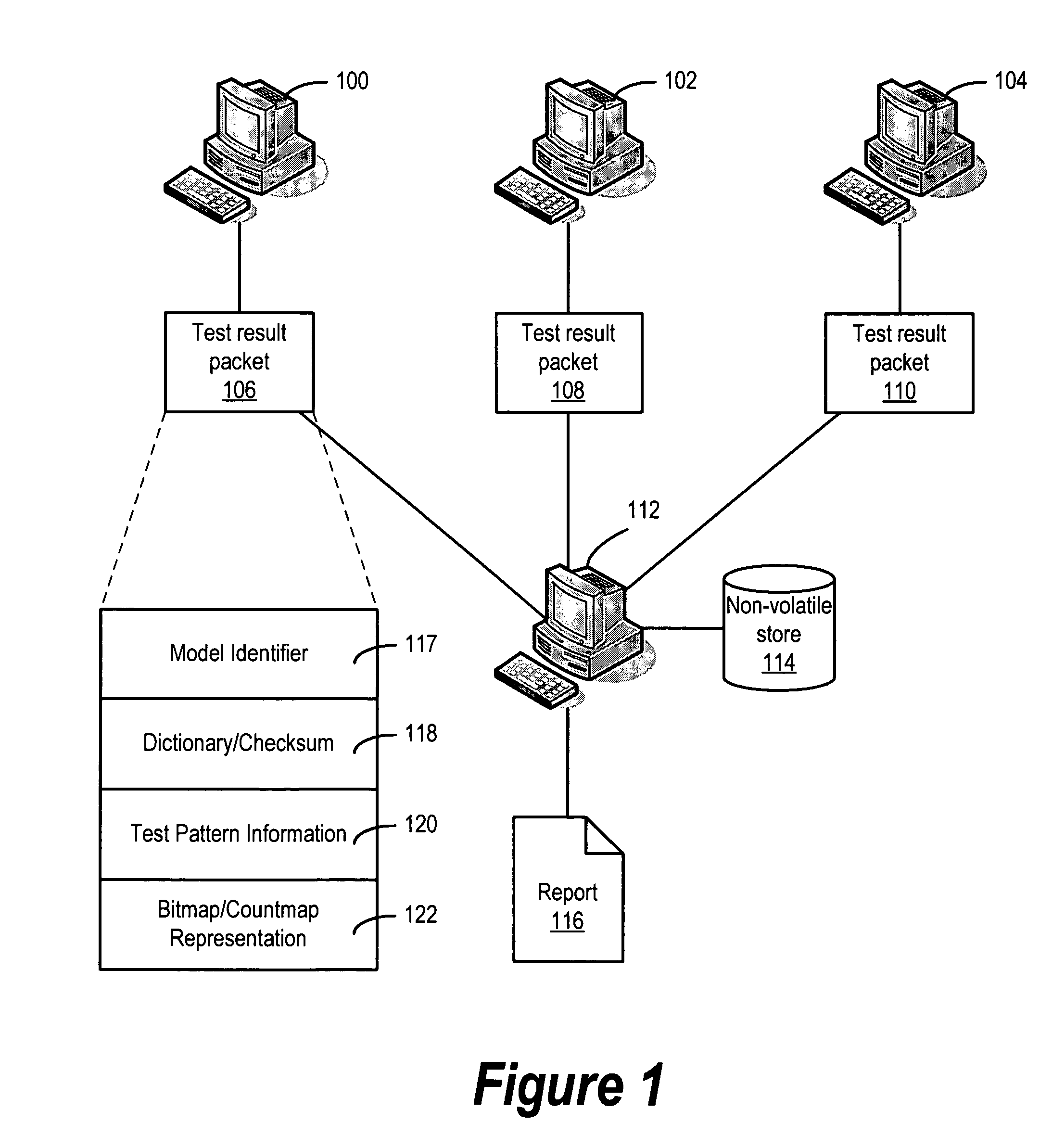
[0018]FIG. 1 is a diagram illustrating the distributed computing architecture utilized by a preferred embodiment of the present invention for obtaining test coverage information. One or more “frontend” computers (represented here by computers 100, 102, and 104) operate in parallel to generate random test patterns and apply them to the design under test (also referred to as the “model”) using appropriate vendor or customer tools created for this purpose. The coverage results of applying each random test pattern are assembled into a packet (packets 106, 108, and 110), which are transmitted to a central “backend” computer 112.

[0019]As shown in FIG. 1, each packet includes a number of items of dat...


PUM


Abstract

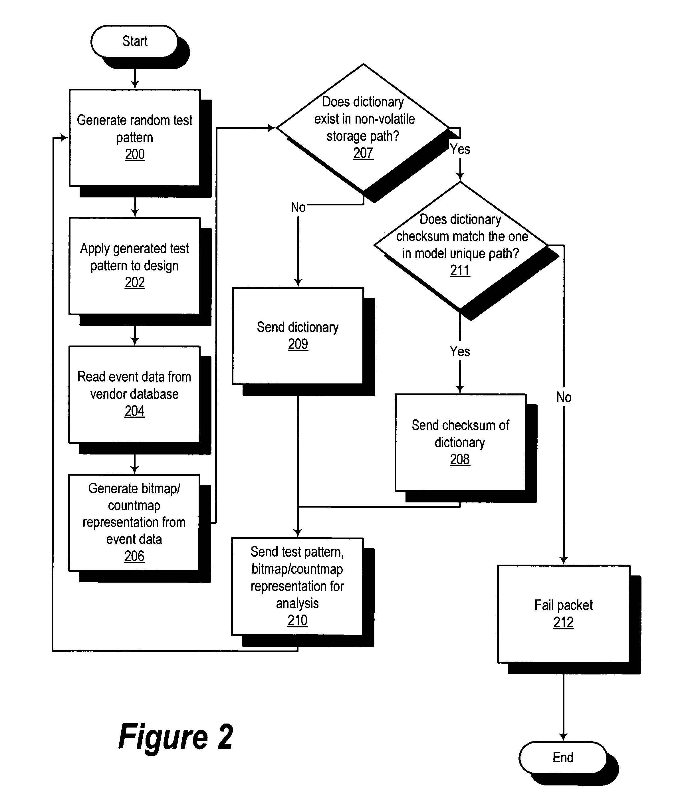
A method, computer program product, and data processing system for minimizing the number of test sequences needed to achieve a desired level of coverage of events in testing a semiconductor design is disclosed. Test patterns are randomly generated by one or more “frontend” computers. Results from applying these patterns to the design under test are transmitted to a “backend” computer for processing. A determination is made as to which test sequences trigger events not already triggered by previously-considered test sequences. An autograde data structure is generated which further reduces the number of test sequences. A preferred embodiment of the present invention may be used to reduce the number of test sequences required, but may also be used to provide test engineers a basis for devising manually-created test sequences to test related events.

Description

CROSS-REFERENCE TO RELATED APPLICATION[0001]The present application is related to commonly-assigned U.S. patent application Ser. No. 11 / 252,019, entitled “Method and Apparatus for Measuring Test Pattern Coverage,” filed even date hereof, which has now issued as U.S. Pat. No. 7,308,658 and is incorporated herein by reference in its entirety.FIELD OF THE INVENTION[0002]The present invention relates generally to the area of automated testing of semiconductor designs. More specifically, the present invention provides a method, computer program product, and apparatus for efficiently ascertaining which testable events a given set of test patterns generates.RELATED ART[0003]Modern electronics is dominated by the development of “very large-scale integrated circuitry” (VLSI). Advances in solid state technology and sub-micron semiconductor manufacturing processes have allowed smaller and smaller components to be fabricated in integrated circuits. This has allowed designs of unprecedented comp...

Claims


Application Information

Patent Timeline
Patent Type & Authority Patents(United States)
IPC IPC(8): G06F17/50
CPCG06F11/263G01R31/31835
Inventor WOOD, GEORGE W.BHINGE, AMOL V.
Owner NORTH STAR INNOVATIONS
Learn More