Lock for securing an article on display

a technology for securing articles and locks, applied in the field of locks for securing articles on display, can solve the problems of inconvenient operation of conventional locks, useless remaining main body (b>50/b>), etc., and achieve the effect of convenient operation

Inactive Publication Date: 2008-08-12
ACCO BRANDS USA LLC
View PDF316 Cites 41 Cited by
  • Summary
  • Abstract
  • Description
  • Claims
  • Application Information

AI Technical Summary

Benefits of technology

[0011]The object of the present invention is to provide a lock which is easy to be operated.
[0012]Another object of the present invention is to provide a lock which is convenient to be well kept.

Problems solved by technology

Additionally, the conventional lock is not convenient to be well kept because the separate hitching part (60) is often lost and the remaining main body (50) becomes useless.

Method used


Image

  • Lock for securing an article on display
  • Lock for securing an article on display
  • Lock for securing an article on display

Examples


Embodiment Construction

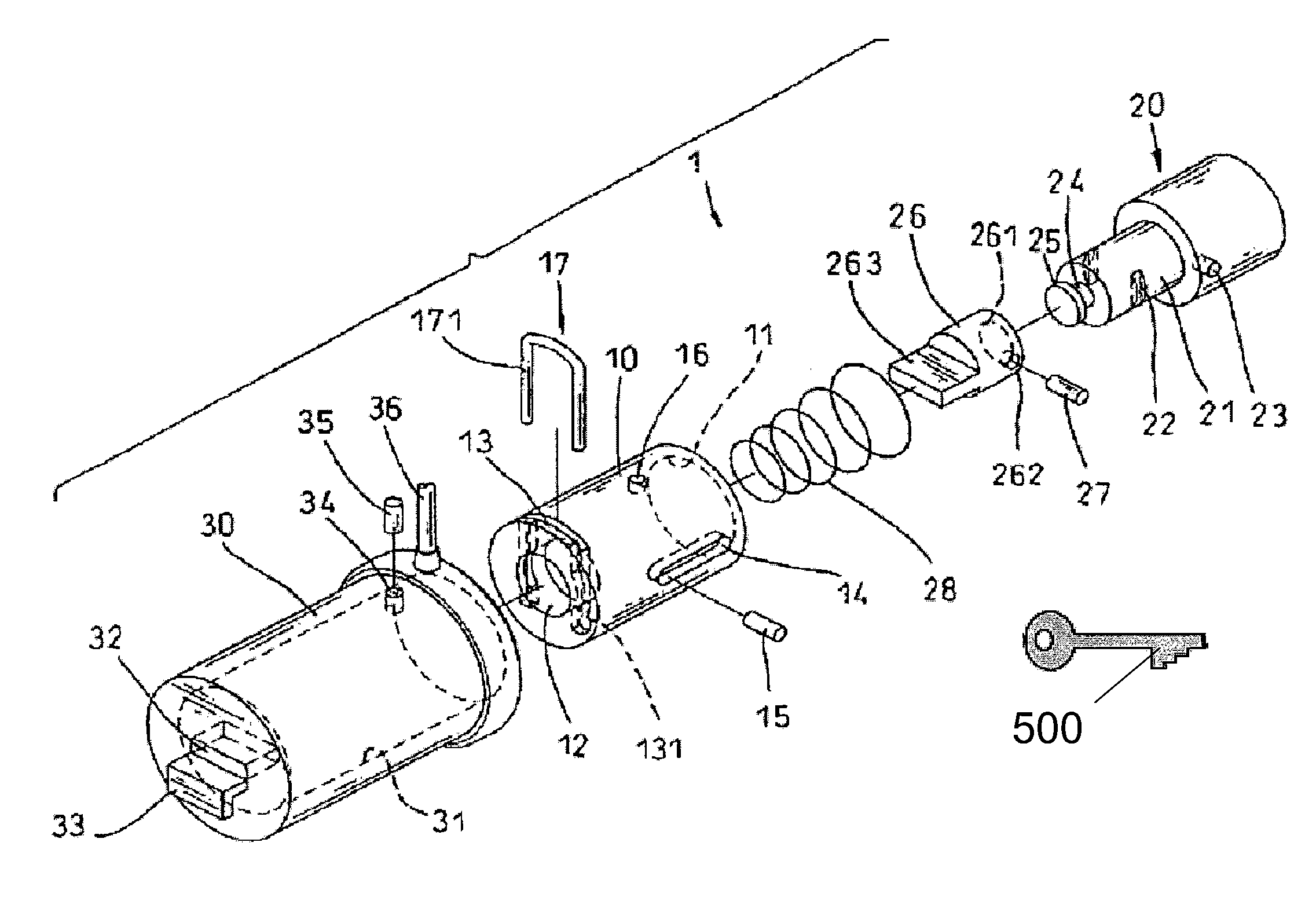
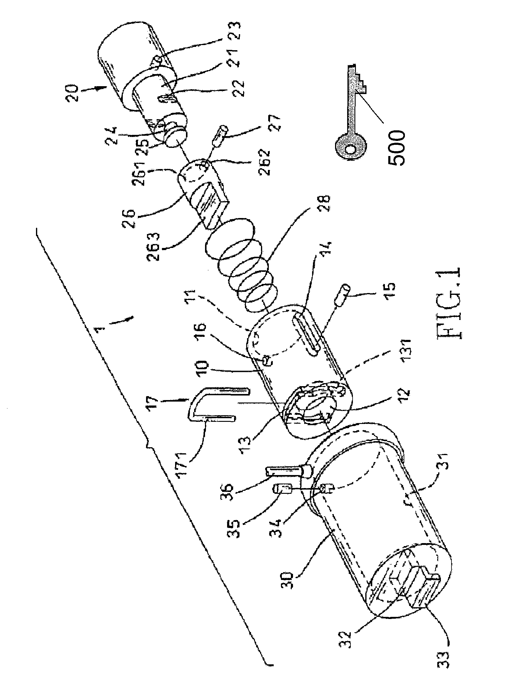
[0019]Referring to FIG. 1, a lock in accordance with the present invention includes a casing (30) having a front opening (32) and a hook (33) contiguous to the opening (32), with a wire cable (36) attached to a periphery of the casing (30). The casing (30) is further formed with a rear opening (31) for receiving a locking body (1).

[0020]The locking body (1) includes a hollow body (10) received in the casing (30). The hollow body (10) has a rear chamber (11), a front through-hole (12) in alignment with the front opening (32) of the casing (30), and preferably a longitudinal groove (14) defined therein.

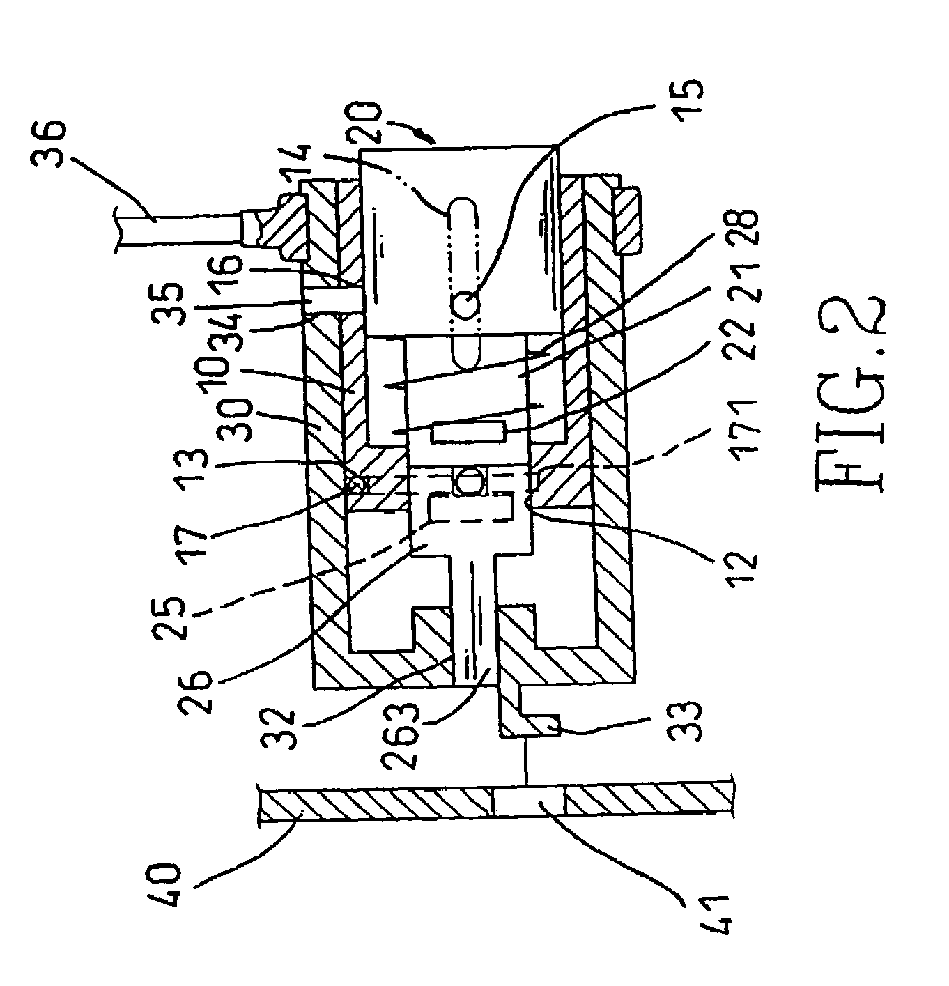
[0021]A cylinder (20) or other pushing element is movably fitted in the rear chamber (11) of the hollow body (10). The cylinder (20) has a hole (23) for receiving a stud (15) that extends into and is movable along the longitudinal groove (14), thus ensuring the correct movement of the cylinder (20) between a front position, as shown in FIG. 4, and a rear position, as shown in FIGS. 2 an...


PUM


Abstract

A lock for securing an article on display includes a casing having a front opening and a hook contiguous to the front opening, with a locking body received in the casing. The locking body is formed with a bolt having a front lip that is movable out of the casing through the front opening. In addition, the locking body is designed so that the front lip of the bolt may be extended out of the casing and securely kept alongside the hook until the lock is opened.

Description

[0001]This application is a continuation application of U.S. patent application Ser. No. 10 / 455,072, filed on Jun. 4, 2003, now U.S. Pat. No. 6,886,376, which is a continuation application of U.S. patent application Ser. No. 10 / 201,281, filed Jul. 24, 2002, now U.S. Pat. No. 6,591,642, which are herein incorporated by reference in their entirety for all purposes.BACKGROUND OF THE INVENTION[0002]1. Field of the Invention[0003]The present invention relates to a lock for securing an article on display and, more particularly, to such a lock which is easy to be operated and convenient to be well kept.[0004]2. Description of Related Art[0005]There is often a need to secure an article on display, especially on public display. This is usually accomplished by a lock that has a wire cable looped through something immovable.[0006]As shown in FIG. 5, a lock for this purpose generally includes a main body (50) having a plurality of dials (51) and a socket (52) for detachably receiving a separate...

Claims


Application Information

Patent Timeline
Patent Type & Authority Patents(United States)
IPC IPC(8): E05B73/00E05B13/10E05B37/02
CPCE05B13/105E05B73/0005E05B73/0082E05B37/025Y10T70/5009Y10T70/7576
Inventor KUO, LAMBERT
Owner ACCO BRANDS USA LLC
Why Eureka
Try Eureka