Valve drive of an internal combustion engine comprising a cylinder head

a technology of internal combustion engine and valve drive, which is applied in the direction of valve details, valve arrangement, valve drive, etc., can solve the problems of cylinder head, base camshaft, and inability to reliably operate the internal combustion engin

Active Publication Date: 2008-08-12
AUDI AG
View PDF12 Cites 54 Cited by
  • Summary
  • Abstract
  • Description
  • Claims
  • Application Information

AI Technical Summary

Problems solved by technology

The essential disadvantage of this camshaft-centered configuration of the detent device is that the base camshafts and the cylinder head are often made of different materials having different thermal expansion coefficients.
This effect may be intensified by inaccuracies in manufacture and assembly or ones determined by operation to the extent that reliable operation of the internal combustion engine is not possible.

Method used


Image

  • Valve drive of an internal combustion engine comprising a cylinder head
  • Valve drive of an internal combustion engine comprising a cylinder head
  • Valve drive of an internal combustion engine comprising a cylinder head

Examples


Embodiment Construction

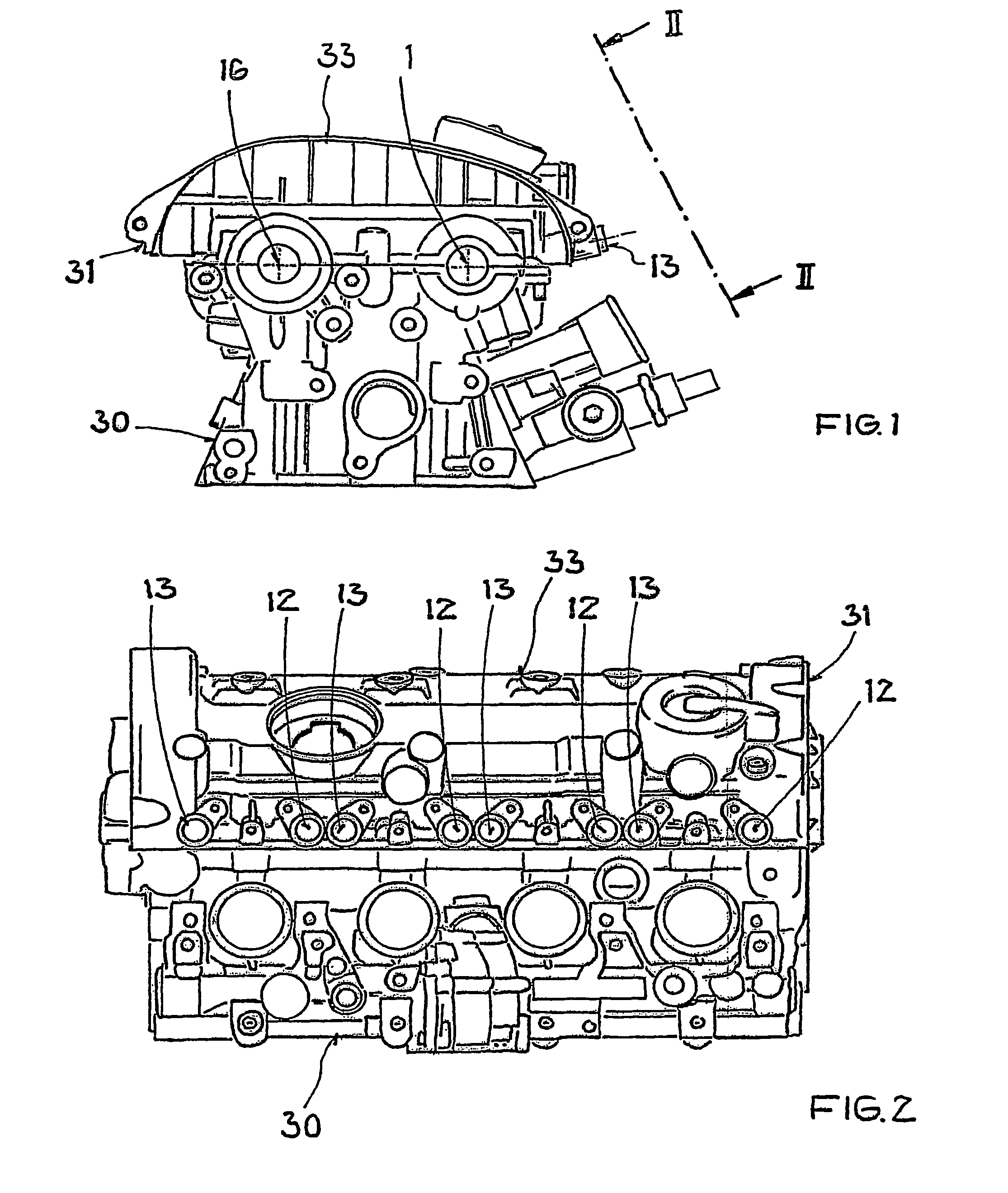
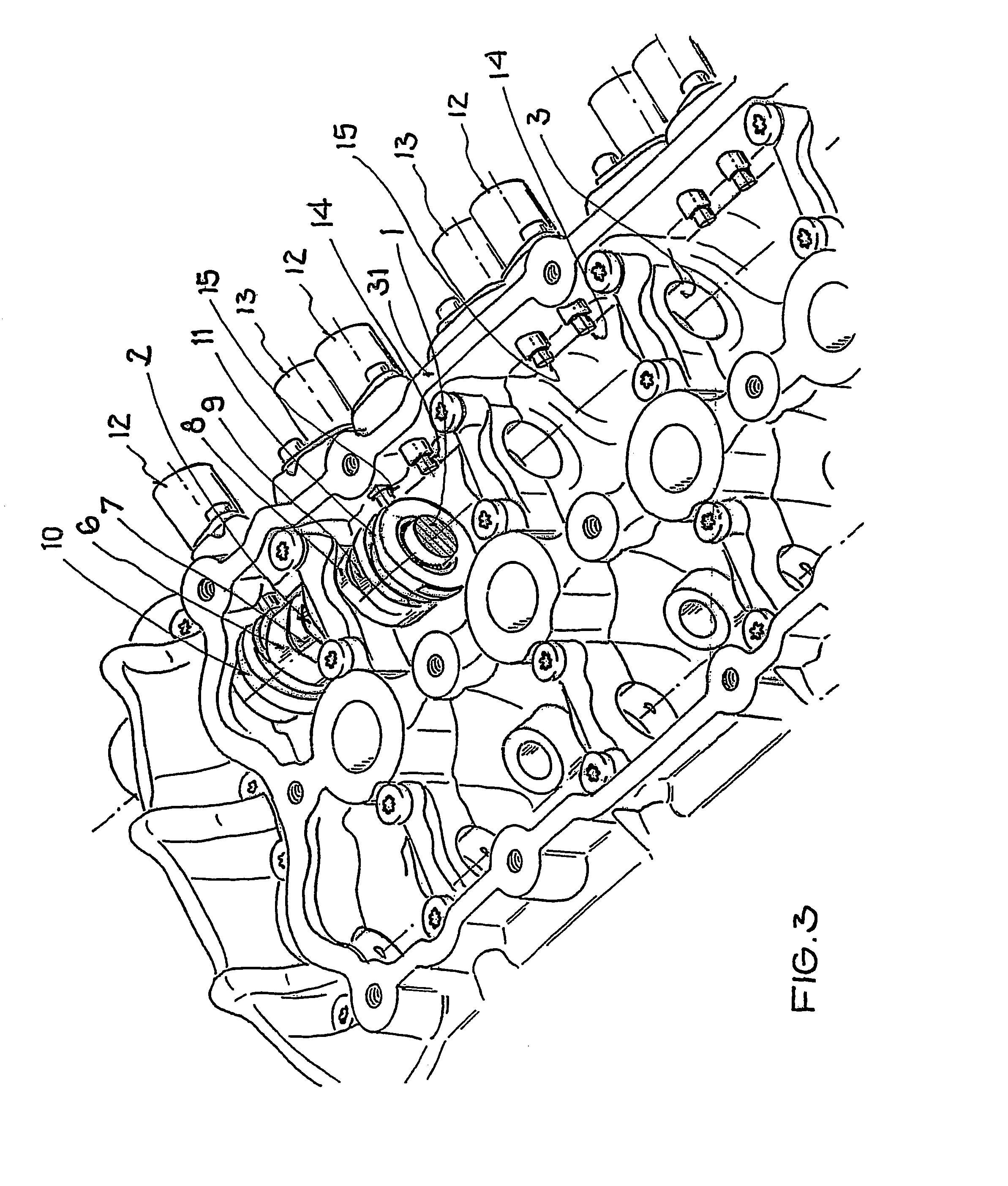
[0031]FIGS. 1 to 3 illustrate an example of an external-ignition four-cylinder in-line internal combustion engine having a crankcase 30 with a cylinder head 31 and cylinder head cover 33 of conventional design. Two intake and two outlet valves (not shown) are installed per cylinder, the intake valves being operated by an intake-valve camshaft and the outlet valves by an outlet-valve camshaft 16 controlled by conventional means. For this purpose the intake camshafts and the outlet camshafts 16 are mounted so as to be in parallel with the longitudinal axis of the engine and are mounted on the two sides of the row of cylinders in the cylinder head 31 so as to be rotatable.

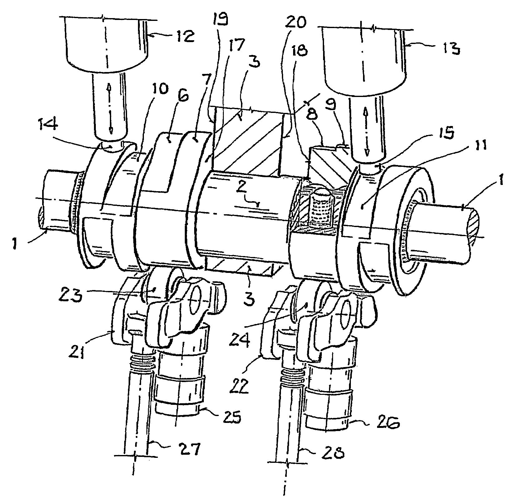
[0032]The outlet camshaft 16 and the intake camshaft, which consists of a base camshaft 1 and four cam carriers 2, are driven by conventional means not shown.

[0033]FIG. 4 shows the intake camshaft, on the base camshaft 1 of which the four cam carriers 2 configured as hollow shafts are mounted spaced axially at a dista...


PUM


Abstract

The invention relates to a valve drive of an internal combustion engine, comprising at least one camshaft whereon at least one cam carrier is arranged in a rotationally fixed and axially displaceable manner. Means for applying axial tension are formed between the at least one camshaft and the at least one cam support, thereby enabling the at least one cam support to be fixed in an axial manner.

Description

[0001]This application is a § 371 application of PCT / EP2004 / 002758, which claims priority from DE 10312581.7, filed Mar. 21, 2003, and DE 10312582.5, filed Mar. 21, 2003.BACKGROUND[0002]This invention relates to a valve drive of an internal combustion engine comprising a cylinder head.[0003]Mechanical devices designed to improve the thermodynamic properties of internal combustion engines have been disclosed, devices which affect the operating cycle of the valve drive and, for example, affect the timing of the valve drive and, for example, enable speed-dependent variation of the opening times or the lift of charge-cycle valves.SUMMARY OF THE INVENTION[0004]Publication DE 42 30 877 discloses such a device, one in which a cam carrier is mounted on a base camshaft so as to be nonrotatable and axially displaceable. The cam carrier consists of a tubular material on which at least one cam is mounted, such that a plurality of cam paths proceeds axially displaced from a common base circle. A...

Claims


Application Information

Patent Timeline
Patent Type & Authority Patents(United States)
IPC IPC(8): F01L1/34F01L1/08F01L13/00
CPCF01L1/08F01L13/0042F01L13/0036F01L2013/0052
Inventor DENGLER, STEFAN
Owner AUDI AG
Why Eureka
Try Eureka