Toolless thermal print head mounting apparatus

Active Publication Date: 2008-08-12
TOSHIBA GLOBAL COMMERCE SOLUTIONS HLDG
View PDF10 Cites 5 Cited by
  • Summary
  • Abstract
  • Description
  • Claims
  • Application Information

AI Technical Summary

Benefits of technology

[0011]In one embodiment, the toolless thermal print head mounting apparatus further includes a handle disp

Problems solved by technology

However, the heating elements may become worn after extended periods of use, making it necessary to periodically replace the print head.
Traditionally, removal of a failed print head requires major disassembly of the printer.
However, although these carriage assemblies may simplify the thermal print head replacement process, these carriage assemblies considerably increase the size and cost of the print head component of their respective thermal printers.
In addition, tools are often required to remove the thermal print head from the thermal printer.
The application of tools to the confined spaces of the thermal printer is a delicate task requiring precision from the user.
This ultimately requires a large input of time and effort by the user to replace the thermal print head.
However, a problem arises in that the different suppliers may supply print heads having differing dimensions; this is especially true of intra-vendor variances in the vertical distance between a print line of the print head and the a cable connector of a print head.

Method used


Image

  • Toolless thermal print head mounting apparatus
  • Toolless thermal print head mounting apparatus
  • Toolless thermal print head mounting apparatus

Examples


Embodiment Construction

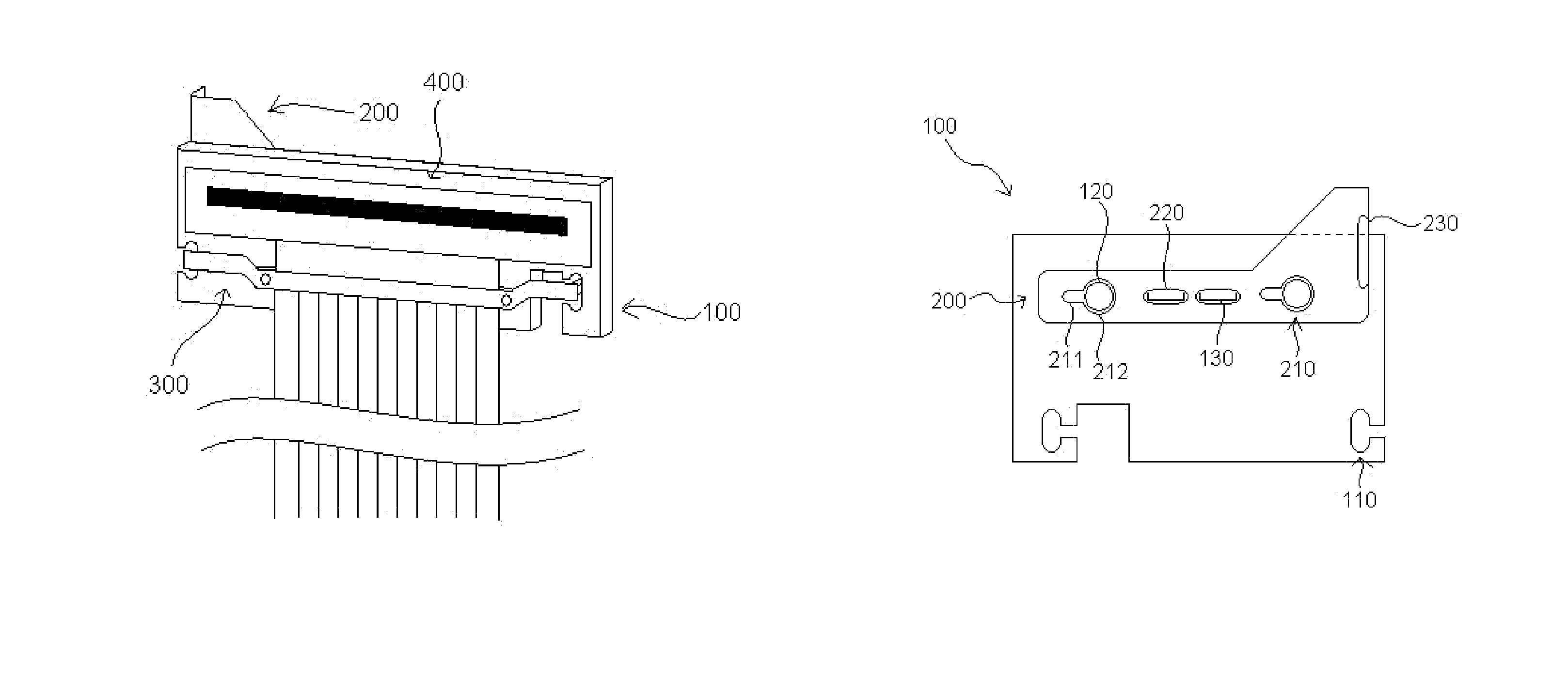
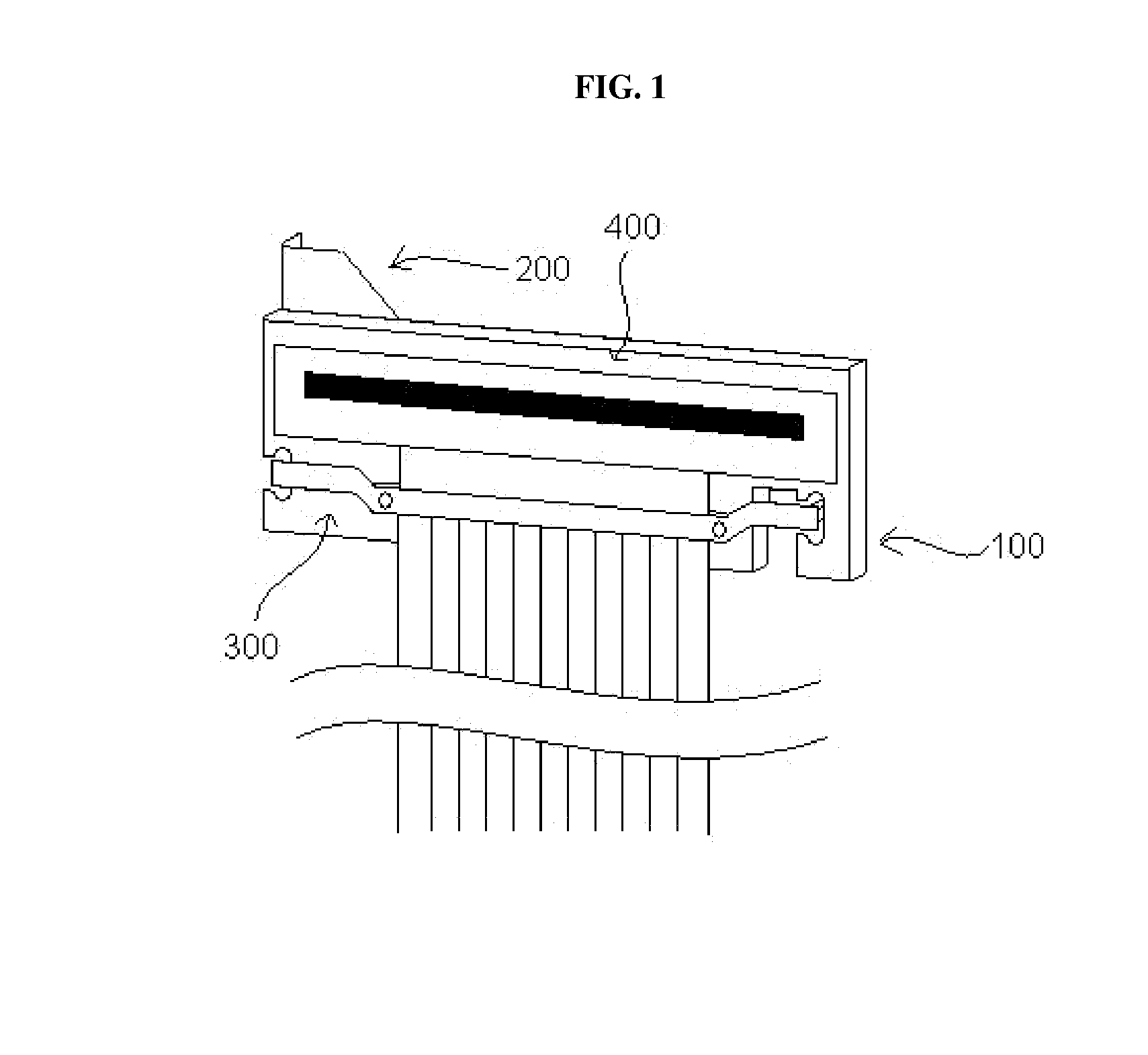
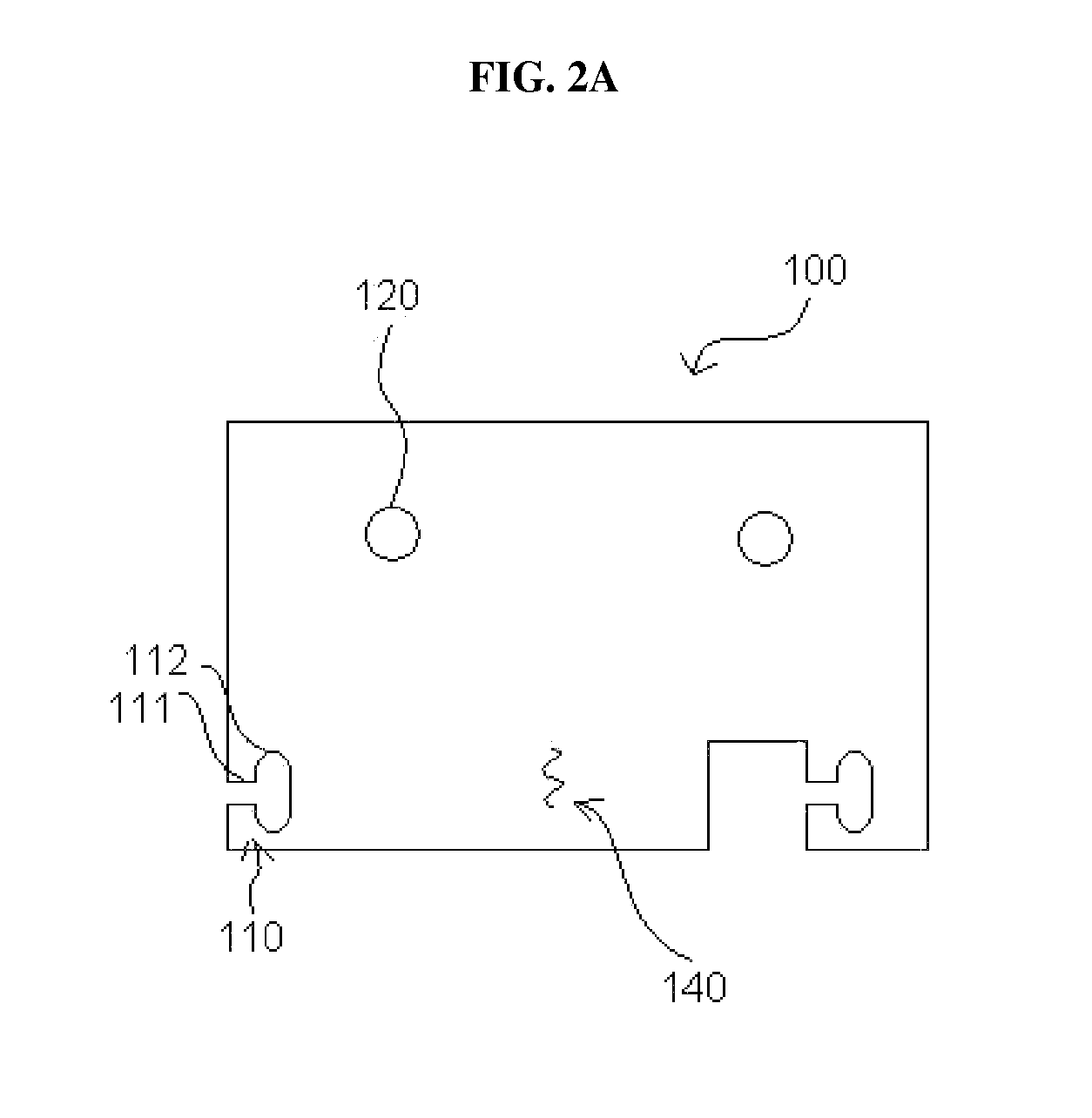
[0024]According to exemplary embodiments, a toolless thermal print head mounting apparatus allows for easy removal and installation of a thermal print head by including a print head mounting bracket which accepts a floating cable clamp configured to pivotally eject a thermal print head and which also accepts a capture latch to fix or release mounting studs on the thermal print head in order to fix the thermal print head to the print head mounting bracket.

[0025]FIG. 1 is a front perspective view illustrating a toolless thermal print head mounting apparatus 100 in accordance with the present invention. As shown in FIG. 1, a toolless thermal print head mounting apparatus includes a print head mounting bracket 100, a capture latch 200, a floating cable clamp 300 and a thermal print head 400. As will be described in more detail below, the thermal print head 400 is coupled to the floating cable clamp 300 and the capture latch 200, and all of the above are coupled to the print head mountin...


PUM


Abstract

A toolless thermal print head mounting apparatus including; a print head mounting bracket including a front face and a rear face, a plurality of print head mounting stud holes and a plurality of cable clamp mounting slots formed in the print head mounting bracket, each of the plurality of cable clamp mounting slots including a side slot and a vertical slot, a capture latch operatively connected to the print head mounting bracket, a plurality of key-slots formed in the capture latch and aligned with the plurality of mounting stud holes, and a floating cable clamp including a plurality of shoulder pins disposed on a rear face thereof, each of the plurality of shoulder pins including a neck configured to pass through the plurality of cable clamp mounting slots and a head configured to be larger than a width of the vertical slot of the cable clamp mounting slots.

Description

BACKGROUND OF THE INVENTION[0001]1. Field of the Invention[0002]This invention relates generally to a system for toolless thermal print head mounting / removal, and more particularly, to a toolless thermal print head mounting apparatus including a print head mounting bracket having side slots and print head mounting stud holes, a floating cable clamp with shoulder pins configured to fit within the side slots and a dual key-slot capture latch disposed on the rear of the print head mounting bracket to capture mounting studs disposed on a print head.[0003]2. Description of the Background[0004]Thermal printers are used in a wide variety of applications. A recent trend in the use of such printers is in point of sale (“POS”) printing of sales receipts. Thermal printers provide for operation at a relatively fast printing speed without the need for ink. The thermal printers include a print head having a print face which typically consists of arrays of numerous heating elements. However, the h...

Claims


Application Information

Patent Timeline
IPC IPC(8): B41J25/304B41J2/32
CPCB41J25/34B41J2/32
Inventor ARRINGTON, STACY L.HARRIS, RICHARD H.HERRING, DEAN F.MYERS, ROBERT A.
Owner TOSHIBA GLOBAL COMMERCE SOLUTIONS HLDG
Why Eureka
Try Eureka