Car Parking Assembly

a technology for car parking and assembly, which is applied in the field of car parking assembly, can solve the problems of increasing the initial capital investment, increasing the storage volume of cars and land for multi-use construction, and real challenges of parking cars in today's world, so as to facilitate the horizontal movement of cars, and reduce the gap between two parked cars

Active Publication Date: 2017-01-05
HCL TECH LTD
View PDF1 Cites 1 Cited by
  • Summary
  • Abstract
  • Description
  • Claims
  • Application Information

AI Technical Summary

Benefits of technology

The present invention is a car parking assembly for reducing gaps between two parked cars. The assembly includes a rail mechanism and a plurality of V-bars. The rail mechanism consists of two parallel rails and several connection bars that connect the rails. The V-ars are mounted on the rail mechanism and have a first bar for parking the rear wheel of the car and a second bar for parking the front wheel of the car. The second bar also has a locking mechanism that restricts movement of the front wheel. The assembly helps to create a gap between two parked cars.

Problems solved by technology

Parking a car in today's world is a real challenge as living space is reducing and cars volumes are increasing.
Among the major disadvantages of such conventional methods is the large storage volume needed per car and land for construction of the multi-level car parking assembly.
Further, automated or manual multi-level car parking assembly includes many mechanically-complicated moving parts which greatly increase the initial capital investment and also require continuous or at least frequent maintenance.
Furthermore, such conventional methods cannot be employed in an already constructed building.
In such places typically use of car parking slots is inefficient due to careless parking, further resulting in huge gaps between two cars in turn wastage of space.
Further, the conventional methods cannot be employed in these spaces, for example basement due to space constraint.

Method used


Image

  • Car Parking Assembly
  • Car Parking Assembly
  • Car Parking Assembly

Examples


Embodiment Construction

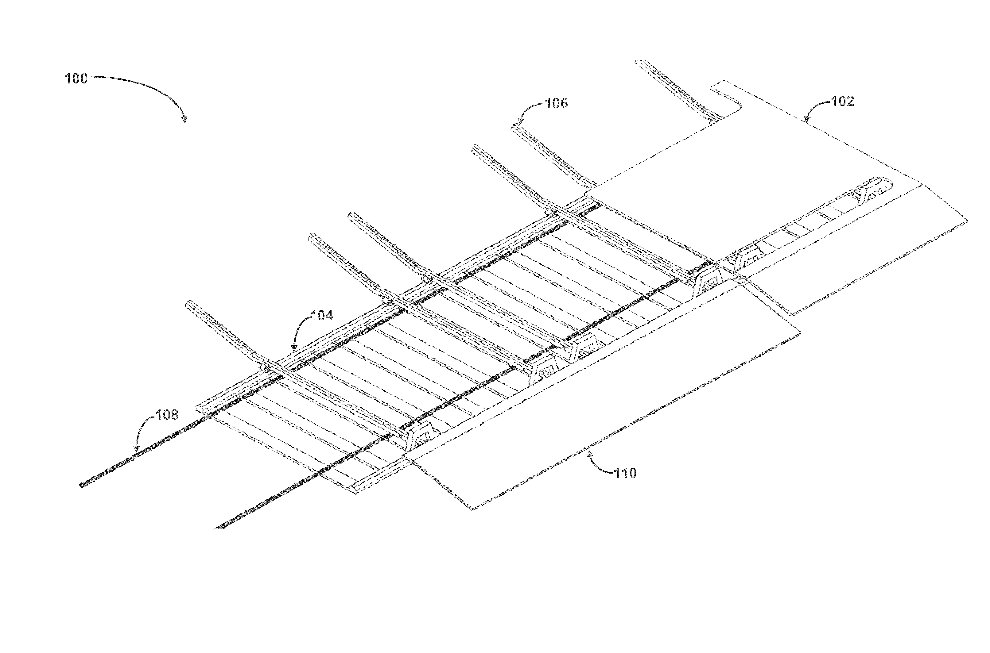
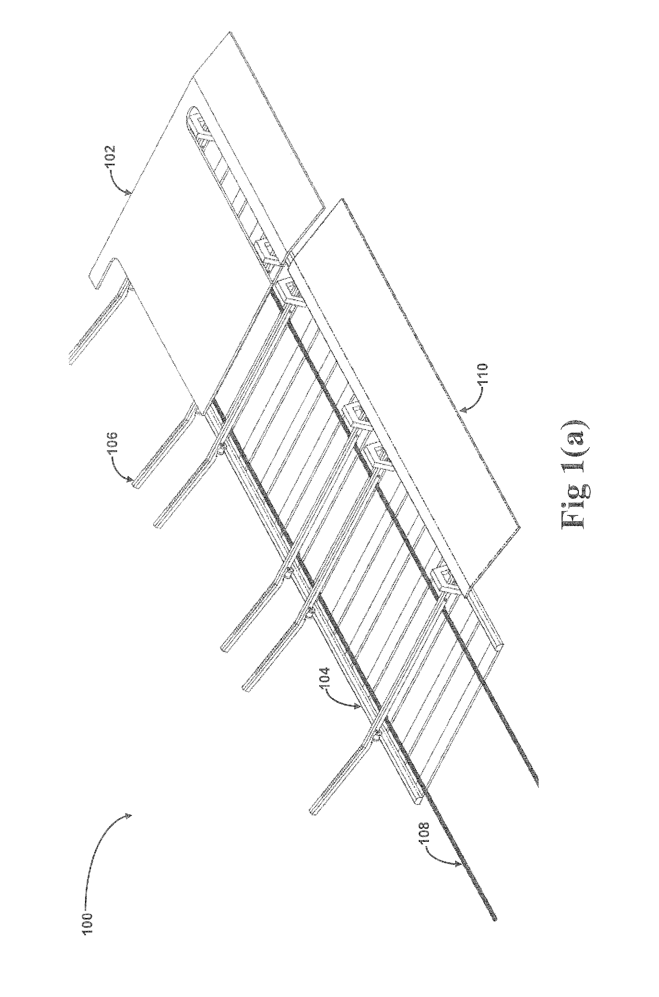
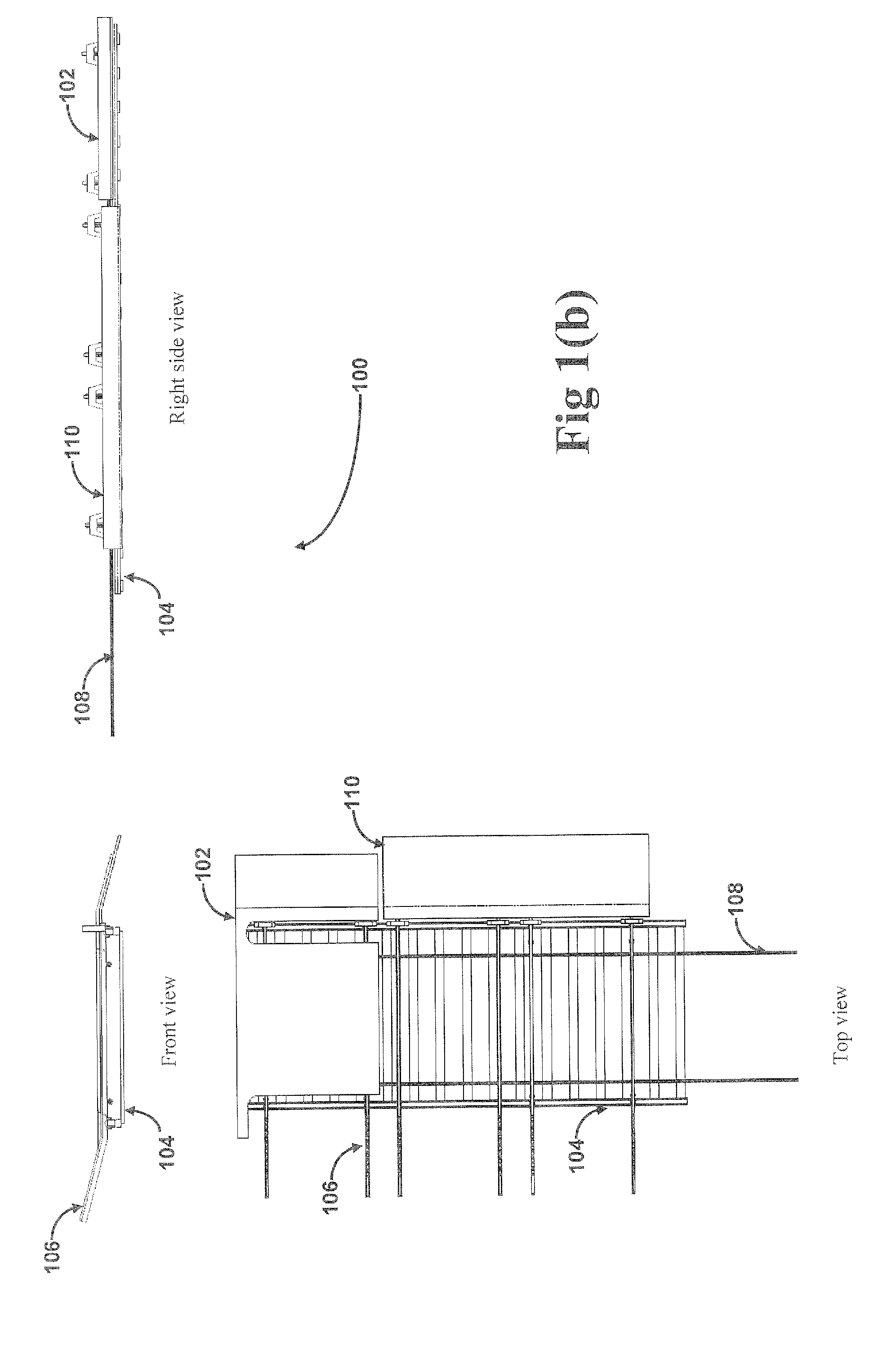
[0017]In an implementation, car parking assembly for reducing a gap between two parked cars is described. In one example, the car parking assembly may be implemented in a basement of a building and place where there is a space constraint. In the implementation the car parking assembly for reducing a gap between two parked cars comprises a rail mechanism, a plurality of V-bars, a parking platform, a pulling mechanism and a retraction ramp for reducing a gap between two parked cars.

[0018]In the implementation, the rail mechanism for facilitating horizontal movement of a car when parked further comprises a first rail, a second rail and a plurality of equally spaced connection bars. In the said implementation, the first rail and the second rail are arranged parallel to each other and each of the connection bars is perpendicular to the first rail and the second rail. Further, each of the connection bars is connected at one end to the first rail and at other end to the second rail.

[0019]I...


PUM


Abstract

Disclosed is a car parking assembly (100). In one aspect, the car parking assembly (100) comprises a rail mechanism (104) and a plurality of V-bars (106) mounted on the rail mechanism (104) to facilitate the parking of a car and horizontal movement of a parked car respectively. The rail mechanism (104) further comprises a first rail (202), a second rail (204) and a plurality of equally spaced connection. The V-bars (106) further comprises a first bar (502) for facilitating parking of a rear wheel of the car and a second bar (506) for facilitating parking of a front wheel of the car and wherein one end of the first bar (502) and one end of the second bar (506) are connected such that to form a obtuse angle.

Description

CROSS-REFERENCE TO RELATED APPLICATIONS AND PRIORITY[0001]The present application claims benefit from Indian Complete Patent Application No. 2008 / DEL / 2015, filed on Jul. 2, 2015, the entirety of which is hereby incorporated by reference.TECHNICAL FIELD[0002]The present subject matter described herein, in general, relates to a parking assembly and more particularly a car parking assembly for reducing a gap between two parked cars.BACKGROUND[0003]Parking a car in today's world is a real challenge as living space is reducing and cars volumes are increasing. As per studies numbers of cars are increasing exponentially all over the world. This increased amount of cars emphasizes on the criticality of parking space availability.[0004]Conventional methods to solve this problem are multi-level car parking assembly or garages. Among the major disadvantages of such conventional methods is the large storage volume needed per car and land for construction of the multi-level car parking assembly....

Claims


Application Information

Patent Timeline
Patent Type & Authority Applications(United States)
IPC IPC(8): B65G1/04B61B13/00
CPCB65G1/04B65G2201/0294B61B13/00E04H6/30
Inventor ROHILLA, SHAILENDRA KUMARTOMAR, SHIVANISAINI, NAVIN
Owner HCL TECH LTD
Why Eureka
Try Eureka