Adjustable work platform for pipe and casing stabbing operations

a technology for working platforms and pipes, which is applied in the direction of drilling pipes, building scaffolds, and well accessories, etc. it can solve the problems of insufficient horizontal movement of the platform, inability to easily, if at all, move around the pipe or tubulars during stabbing operations, and prior art stabbing boards and stabbing baskets. to achieve the effect of facilitating horizontal and vertical movement of the platform

Inactive Publication Date: 2010-07-15
SUPERIOR RIG SOLUTIONS INC
View PDF11 Cites 9 Cited by
  • Summary
  • Abstract
  • Description
  • Claims
  • Application Information

AI Technical Summary

Benefits of technology

[0006]In one embodiment, the present invention provides a stabbing basket for a rig and for supporting a worker while stabbing joints of tubular members together during running operations, comprising a frame member for mounting the stabbing basket to the rig, a platform to support the worker, a carriage to slidably mount the platform to the frame member, vertical power means for moving the carriage vertically with respect to the frame member, an articulating boom to interconnect the platform with the carriage and to facilitate horizontal and vertical movement of the platform relative to the carriage and frame member, said articulating boom comprising a first segment and a second segment and at least one pivoting actuator positioned between the first segment and the second segment.

Problems solved by technology

However, the prior art stabbing boards and stabbing baskets suffer from a number of disadvantages, such as not provide for sufficient horizontal movement of the platform to allow an operator to be placed in sufficient proximity to the pipe or tubulars during stabbing operations, not being easily stowed away in compact format (so as to reduce interference with rig operations when such a platform is not needed) and not being able to easily, if at all, move around the pipe or tubulars during stabbing operations (so as to allow an operator to reach the other side of such pipe or tubular).

Method used


Image

  • Adjustable work platform for pipe and casing stabbing operations
  • Adjustable work platform for pipe and casing stabbing operations
  • Adjustable work platform for pipe and casing stabbing operations

Examples


Embodiment Construction

[0021]The following description is of a preferred embodiment by way of example only and without limitation to the combination of features necessary for carrying the invention into effect. Reference is to be had to the Figures in which identical reference numbers identify similar components. The drawing figures are not necessarily to scale and certain features are shown in schematic form in the interest of clarity and conciseness.

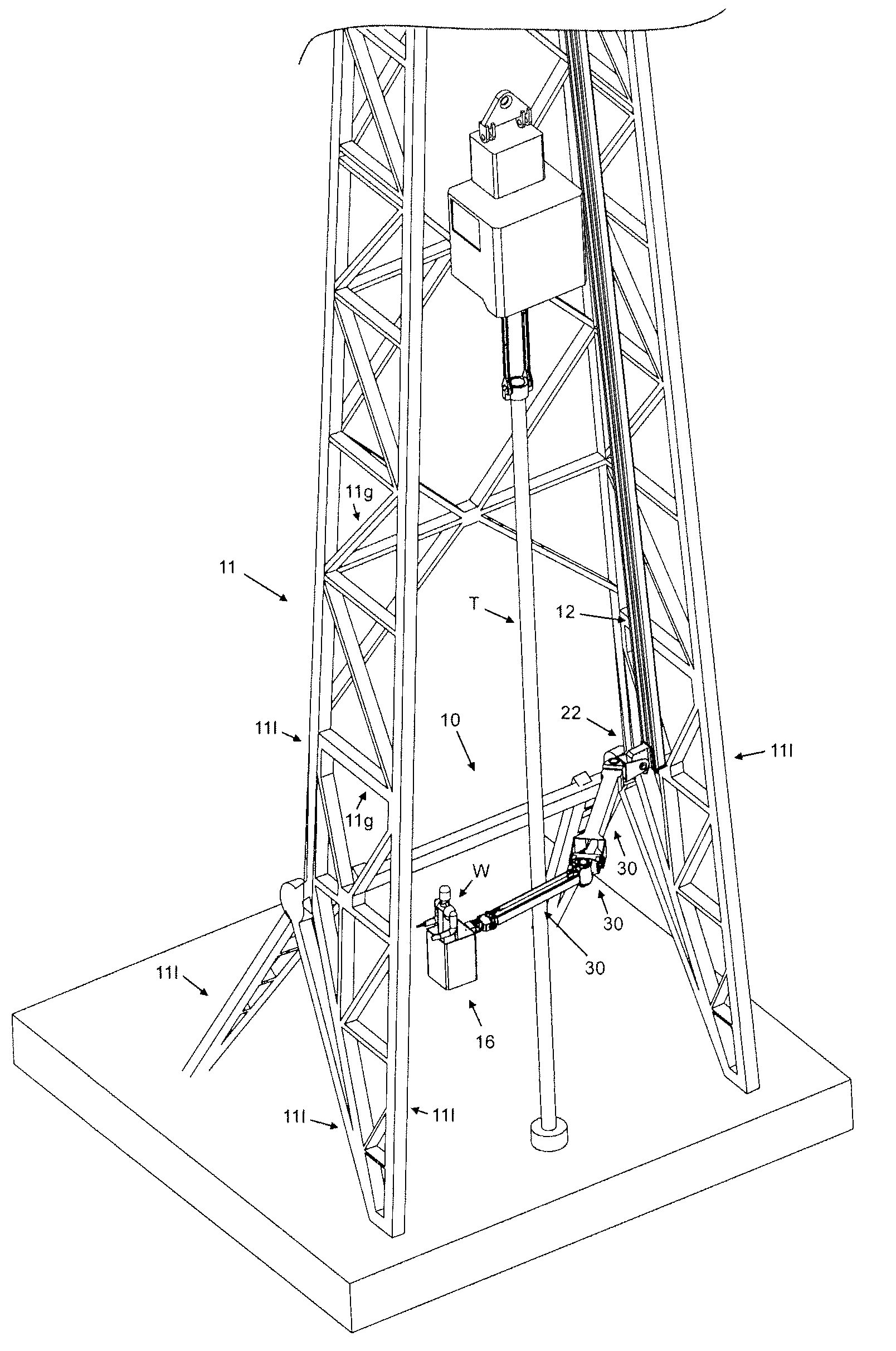
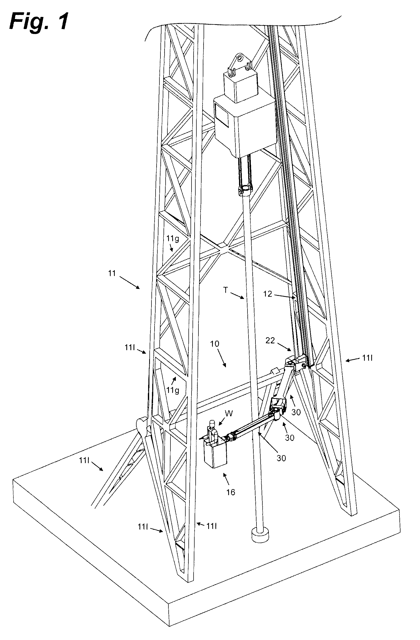
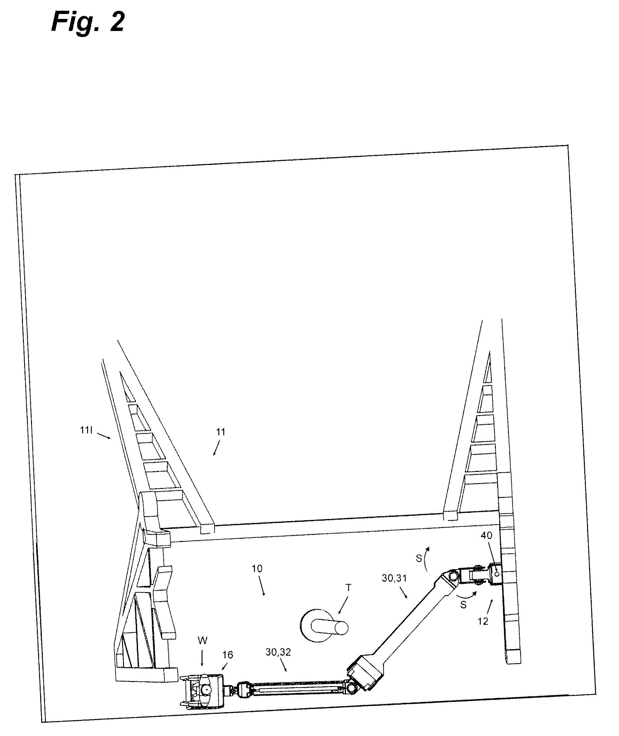
[0022]FIGS. 1-13 illustrate the configuration of a preferred embodiment of the present invention. In this embodiment, stabbing basket 10 is adapted to be attached to a derrick or rig 11, from either the inside or outside as may be desired (shown in the figures as mounted to the inside), and for supporting a worker W in stabbing joints of tubular members T together during running operations.

[0023]The stabbing basket 10 of this embodiment comprises a frame member 12 to attach or mount the stabbing basket 10 to the rig 11, a platform 16 to support the worker W,...


PUM


Abstract

A stabbing basket, for a rig and for supporting a worker while stabbing joints of tubular members together during running operations, comprises a frame member for mounting the stabbing basket to the rig, a platform to support the worker, a carriage to slidably mount the platform to the frame member, vertical power means for moving the carriage vertically with respect to the frame member, an articulating boom, interconnecting the platform with the carriage, said articulating boom comprising a first segment and a second segment, and at least one pivoting actuator positioned between the first segment and the second segment.

Description

FIELD OF THE INVENTION[0001]The present invention relates generally to a handling board or platform and, more particularly, to a stabbing basket assembly mountable on a well derrick for supporting a worker while stabbing joints of pipe or casing during running operations.BACKGROUND OF THE INVENTION[0002]It is common practice in the oil and gas well drilling art to provide some form of support or platform for accommodating an operator or worker at a position above the floor of the derrick, particularly during a running of pipe or tubulars into the well, in order to assist in properly axially aligning the tubulars during the stabbing operation. Typically this is accomplished through the use of casing stabbing boards, which are hung or suspended on wirelines held within the derrick or drilling rig. Stabbing or casing baskets which travel up and down along a vertical track on the inside or outside of a derrick and which have a telescoping boom to move a basket away or towards vertical t...

Claims


Application Information

Patent Timeline
Patent Type & Authority Applications(United States)
IPC IPC(8): E04G3/28B66F11/04E21B41/00
CPCB66F11/04E21B41/00E21B19/00
Inventor MORELLI, VINCELUDWIG, DARCY
Owner SUPERIOR RIG SOLUTIONS INC
Why Eureka
Try Eureka