
Device for filling containers by weight, the device being fitted with an anti-vibration member

a technology of weight sensor and container, which is applied in the direction of weighing apparatus, liquid bottling, packaged goods, etc., can solve the problems of high-precision ball bearings that are very expensive and sensitive to being dirtied, and disturb the measurement of weight sensors

Inactive Publication Date: 2013-06-13
SERAC GROUP
View PDF11 Cites 4 Cited by
  • Summary
  • Abstract
  • Description
  • Claims
  • Application Information

AI Technical Summary

Benefits of technology

The invention is about a structure for supporting containers during filling. The structure includes a connection arm with a single folding portion that allows for vertical movement without stressing the support member and provides rapid damping of vibration. The connection arm is positioned at the level of the container-holding portion and extends radially relative to a path traveled by containers during filling. The support member includes a rod engaged in a support tube, and the first end of the connection arm is rigidly connected to the support tube by a spacer. This results in a compact device. The technical effects of the invention are improved resistance to lateral force, reduced stress on the support member, and reduced vibration during filling.

Problems solved by technology

It has then been found that when the filler device is mounted on a movable structure, for example a rotary structure of a filler carousel, the support member tends to vibrate when a container is put into place, thereby disturbing the measurement of the weight sensor, such that it becomes necessary to wait for the device to stabilize before it is possible to proceed with filling.
This waiting time considerably reduces the throughput rate at which containers can be filled.
Nevertheless, in order to ensure that the resulting hinged parallelogram does not give rise to interfering forces on the weight sensor, it is necessary to use high-precision ball bearings that are very expensive and very sensitive to being dirtied by the fluids for packaging or by the fluids for cleaning the filler spouts.

Method used


Image

  • Device for filling containers by weight, the device being fitted with an anti-vibration member
  • Device for filling containers by weight, the device being fitted with an anti-vibration member
  • Device for filling containers by weight, the device being fitted with an anti-vibration member

Examples


Embodiment Construction

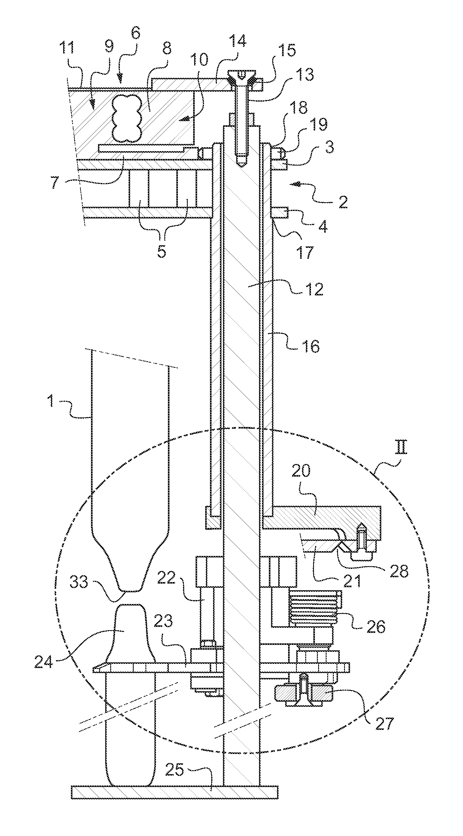
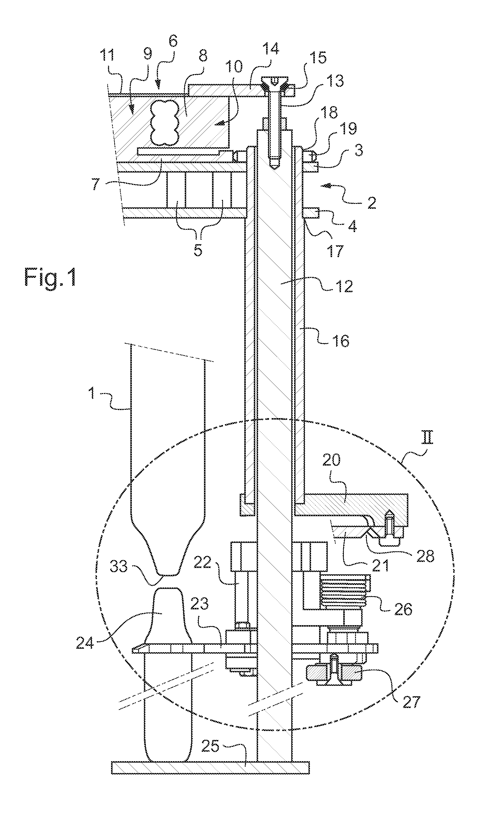
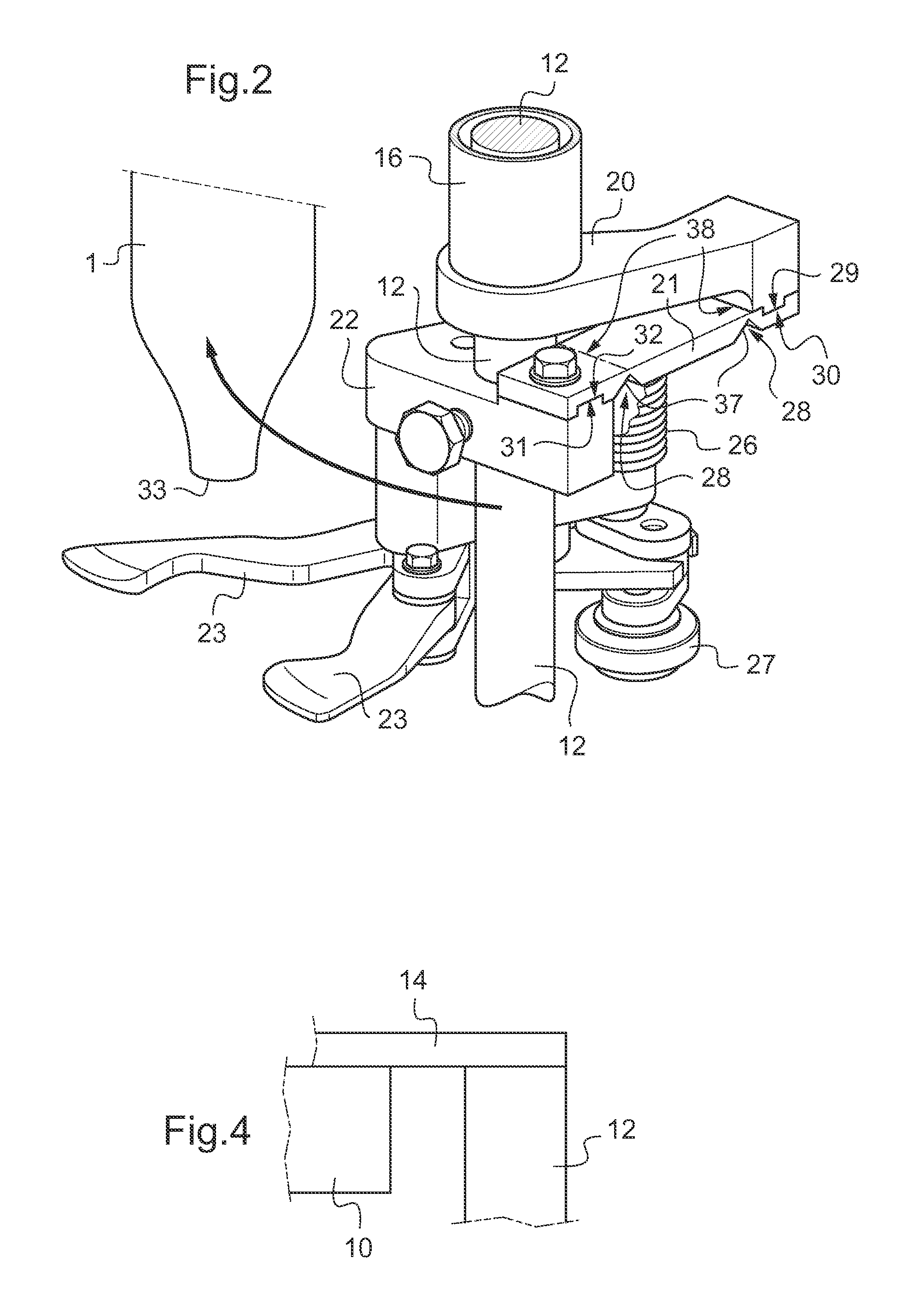
[0021]With reference to FIGS. 1 and 2, in this first embodiment, the device comprises in conventional manner a series of filler spouts 1, only one of which is shown in FIG. 1, and its structure is not shown in detail. The filler spouts are carried by a structure represented herein by a rotary platform 2 having two turntables 3 and 4 held spaced apart from each other by spacers 5.

[0022]Each filler spout 1 is associated with a weight sensor 6 having a base 7 fastened to the turntable 3 and made integrally with an elastically deformable bar 8 having one end 9 rigidly fastened to the structure 2 via the base 7 and an opposite end 10 that is cantilevered out. The weight sensor also includes a sensing element, a strain gauge 11 in this example, that is associated with the elastically deformable bar 8 in order to measure its deformation.

[0023]In the first embodiment shown in FIGS. 1 and 2, the weight sensor 6 is associated with a container-support member comprising a rod 12 having a top en...


PUM

PropertyMeasurementUnit
Weightaaaaaaaaaa
Levelaaaaaaaaaa
Deformation enthalpyaaaaaaaaaa

Abstract

A device for filling containers by weight, the device comprises: a filler spout carried by a structure and having a delivery orifice; a container support member extending on one side of the filler spout, the container support member being associated with a weight sensor arranged at a level that is higher than the delivery orifice; and a connection arm having a first end fastened to the structure and a second end fastened to the container support member at a level below the weight sensor, the connection arm having two folding portions configured to enable effortless folding about mutually parallel horizontal axes, while providing a connection that is rigid against forces in a horizontal plane.

Description

[0001]The present invention relates to a device for filling containers by weight, the device being fitted with an anti-vibration member.BACKGROUND OF THE INVENTION[0002]A device for filling containers by weight is disclosed in particular in document EP 1 025 424, which device comprises a filler spout carried by a structure and having a delivery orifice below which the containers are supported by a container support member. The container support member is connected to a weight sensor comprising both an elastically deformable bar having one end rigidly fastened to the structure and an opposite end that is cantilevered out, and a sensing element associated with the elastically deformable bar to measure its deformation.[0003]In order to protect the weight sensor against splashes of the fluid to be packaged or of a fluid for cleaning the filler spout, filler devices have been made in which the weight sensor is arranged at a level that is higher than the delivery orifice. Nevertheless, un...

Claims


Application Information

Patent Timeline
IPC IPC(8): B65B3/28
CPCB65B3/28G01G23/12G01G13/003B67C3/202
Inventor GRAFFIN, JEAN-JACQUES
Owner SERAC GROUP
Learn More