Method and module for DDS (direct digital synthesizer) pulse edge adjusting and pulse signal generator

A technology of pulse signal and adjustment method, applied in electric pulse generator circuit, pulse processing, pulse technology and other directions, can solve the problems of small duty cycle of low frequency pulse, small range of pulse edge adjustment, and re-update, etc. The effect of small air ratio and large-scale precise adjustment

Active Publication Date: 2013-06-26
SHENZHEN CITY SIGLENT TECH
View PDF4 Cites 40 Cited by
  • Summary
  • Abstract
  • Description
  • Claims
  • Application Information

AI Technical Summary

Problems solved by technology

However, the pulse edge adjustment range of these two methods is very small, and the rapid rise and fall of the pulse signal edge cannot be achieved at low frequency pulses.
In addition, the size of the edge in the second method will be affected by the frequency of the pulse signal; the edge time is very large (millisecond level) when the low frequency pulse is used, and the fast edge cannot be set, that is, the time of the pulse signal edge is very small (nanosecond level); it is affected by the waveform Due to length limitation, the duty cycle of low-frequency pulses cannot be set very small (generally the minimum can only be adjusted to 0.1%); if you want to obtain different pulse waveforms, that is, when changing the frequency, edge and pulse width of the pulse, you need to re-update Waveform data, especially when the length of the waveform data is large, it takes a long time to change various parameters of the pulse

Method used


Image

  • Method and module for DDS (direct digital synthesizer) pulse edge adjusting and pulse signal generator
  • Method and module for DDS (direct digital synthesizer) pulse edge adjusting and pulse signal generator
  • Method and module for DDS (direct digital synthesizer) pulse edge adjusting and pulse signal generator

Examples


Embodiment Construction

[0041] The present invention will be further described in detail below through specific embodiments in conjunction with the accompanying drawings.

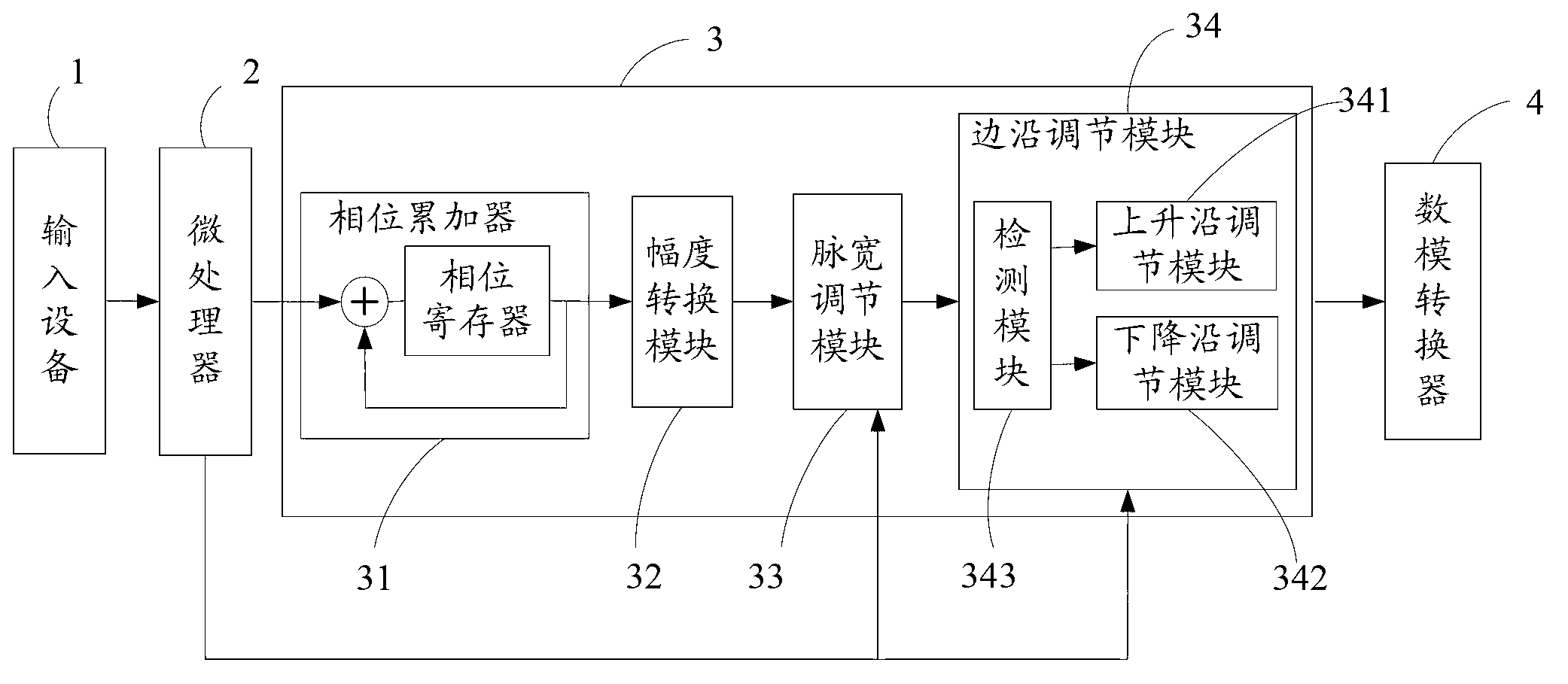
[0042] Such as figure 1 As shown, a pulse signal generator provided by the present application includes an input device 1 , a microprocessor 2 , a DDS module 3 and a digital-to-analog conversion module 4 connected in sequence. Wherein, the DDS module 3 includes a phase accumulator 31 , an amplitude conversion module 32 , a pulse width adjustment module 33 and an edge adjustment module 34 . The edge adjustment module 34 further includes a rising edge adjustment module 341 , a falling edge adjustment module 342 and a detection module 343 .

[0043] The input device 1 is used to provide an input interface to receive the pulse signal parameters input by the user; in a specific embodiment, the pulse signal parameters input by the user include frequency, pulse width, rising edge time and falling edge time of the pulse signal. The micr...


PUM


Abstract

The invention discloses a method and a system for DDS (direct digital synthesizer) pulse edge adjusting and a pulse signal generator. The pulse signal generator comprises input equipment, a microprocessor, a DDS module and a digital-analog converter in sequential connection, the DDS module comprises a phase accumulator, an amplitude converting module, a pulse-width adjusting module and an edge adjusting module, the edge adjusting module comprises a detection module, a rising edge adjusting module and a falling edge adjusting module, the detection module is used for detecting arrival time of a rising edge and arrival time of a falling edge of initial pulse signal data, the rising edge adjusting module is used for realizing rising edge adjusting of the initial pulse signal data according to an upper stepping value, and the falling edge adjusting module is used for realizing falling edge adjusting of the initial pulse signal data according to a lower stepping value. Compared with the prior art, by the technical scheme, quick rising and falling of pulse signal edges can be realized when frequency is low, the duty ratio is extremely low, and large-scale accurate pulse signal edge adjusting can also be realized.

Description

technical field [0001] The present application relates to the field of electronic instruments, in particular to a DDS pulse edge adjustment method, module and pulse signal generator. Background technique [0002] DDS (Direct Digital Synthesizer, direct digital frequency synthesizer) can generate arbitrary pulse waveforms. At present, the methods used to adjust the pulse edge are: one is the adjustment of the hardware circuit composed of discrete components; the other is for different rising Falling edge, fill the corresponding pulse waveform data into the waveform memory of DDS to adjust the pulse edge. However, the pulse edge adjustment range of these two methods is very small, and the rapid rise and fall of the pulse signal edge cannot be realized when the pulse frequency is low. In addition, the size of the edge of the second method will be affected by the frequency of the pulse signal; the edge time is very large (millisecond level) when the low-frequency pulse is used,...

Claims


Application Information

Patent Timeline
Patent Type & Authority Applications(China)
IPC IPC(8): H03K3/02H03K5/12
Inventor 梁振兴
Owner SHENZHEN CITY SIGLENT TECH
Why Eureka
Try Eureka