Remote controlled mirror for heavy equipment

Active Publication Date: 2015-12-01
CHANTILLY
View PDF6 Cites 14 Cited by
  • Summary
  • Abstract
  • Description
  • Claims
  • Application Information

AI Technical Summary

Benefits of technology

The patent describes a remote controlled mirror that is designed for use on large heavy vehicles or equipment. The mirror is reliable and accurate even in off-road conditions with high levels of vibration. It can withstand high loads and can operate even in environments with high levels of particulate matter. The patent is specifically designed for larger mirrors that require remote control adjustments due to a lack of available designs for this specific use.

Problems solved by technology

The remote controlled mirror is specifically adapted and designed for large heavy mirrors for which remote control adjustment is needed due to a dearth of designs available to meet the specific challenges posed.

Method used


Image

  • Remote controlled mirror for heavy equipment
  • Remote controlled mirror for heavy equipment
  • Remote controlled mirror for heavy equipment

Examples


example 1

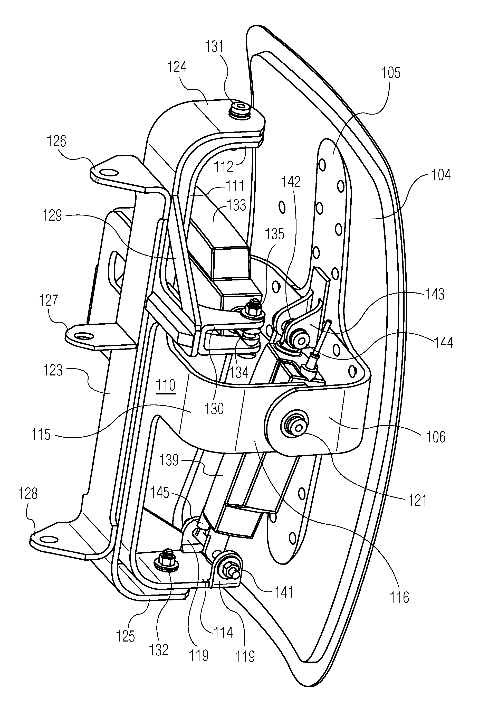
[0095]FIG. 2 shows a representative remote controlled mirror to which a remote controller can be attached.

[0096]Mirror assembly 101 comprises a mirror 102, a mirror frame 103 (partially shown, complete mirror frame corresponds to perimeter of mirror) which covers the outer edge of the mirror 102, and a mirror back 104, which has a mirror bracket 105 comprising a first a first mirror-pivot tab 106 and a second mirror pivot tab 107. Mirror 102 is attached to mirror back 104. Mirror frame 103 which covers the outer edge of the mirror 102. Mirror bracket 105 comprising a first a first mirror-pivot tab 106 and a second mirror pivot tab 107 is attached to a mirror back 104 by a plurality of rivets 108.

[0097]Dual axis pivot bracket 110 comprises: a first longitudinal bracket arm 111 comprising a first longitudinal pivot bracket connection tab 112, a second longitudinal bracket arm 113 comprising a second longitudinal pivot bracket connection tab 114 with a first pivot bracket-to-linear act...

example 2

[0119]In some embodiments, a remote controlled mirror is provided. The remote controlled mirror assembly comprises a) a mirror assembly; b) a dual axis pivot bracket; c) a y axis linear actuator; d) a fixed mounting bracket; and e) an x axis linear actuator. The remote controlled mirror optionally comprises a shaft useful to support the mirror assembly and allow it to rotate axially about the vertical axis created by its inclusion. The mirror assembly comprises a mirror with a fixed mirror back, the mirror weighing at least 25 pounds and having dimensions of a width of at least 12 inches and a height of at least 24 inches; a mirror back, and two or more mirror mounting brackets comprising a support tab and a mirror-pivot tab. The surface area of support tabs that is attached to the mirror back is at least 50% of surface area of mirror back surface. The mirror-pivot tab is used to attach the mirror assembly to a dual axis pivot bracket either directly or indirectly using an optional ...

example 3

[0120]FIG. 3 shows a representative remote controlled mirror which weighs about 76 pounds and has a mirror with dimensions of a width of about 12″ wide and a height of 40″ inches high.

[0121]Mirror assembly 1 comprises a mirror 2, a mirror frame 3 which covers the outer edge of the mirror 2, and a mirror back 4, which has a mirror slot 5 into which the mirror 2 within the mirror frame 3 are inserted. Retaining bracket 6 holds the mirror 2 within the mirror frame 3 within the mirror slot 5 of the mirror back 4. Two retaining bracket connector assemblies 7 are provided which fixedly attach the retaining bracket 6 to the mirror back 4.

[0122]Mirror assembly 1 has six mirror brackets 8 arranged as three pairs of mirror brackets 8. Each mirror bracket 8 comprises a support tab 9 in the shape of essentially a half circle and a mirror pivot tab 10. The support tab 9 attaches to the mirror back 4. The mirror pivot tab 10 comprises a mirror pivot tab opening 11 for receiving a y axis shaft 12....


PUM


Abstract

A remote controlled mirror is provided which comprises: 1) a mirror assembly, 2) a dual axis pivot bracket, and 3) a fixed mounting bracket and further comprises a horizontal drive actuator and a vertical drive actuator. The remote controlled mirror is for use in heavy equipment and comprises mirror that weigh over 10 pounds, in some embodiments 50 pounds or more and in some embodiments 80 pound or more.

Description

CROSS REFERENCE TO RELATED APPLICATIONS[0001]This application claims priority to U.S. Provisional Application No. 61 / 704,321 filed Sep. 21, 2012, which is incorporated herein by reference.FIELD OF THE INVENTION[0002]Remote controlled mirrors are provided which are particularly useful for heavy mirrors used with heavy equipment.BACKGROUND OF THE INVENTION[0003]Heavy equipment including, but not limited to, earth moving equipment, construction equipment and vehicles, large off-road trucks and vehicles, surface mining equipment and vehicles, mineral and earth processing equipment and other equipment used in quarries and mines, and other vehicles and large sized equipment frequently used in off road applications and not suitable for use on existing roadways often employ very large, very heavy mirrors that are used by operators when operating the vehicles or equipment. These mirrors are typically located at a distance from the operator's seat or position that places them beyond reach whe...

Claims


Application Information

Patent Timeline
IPC IPC(8): G02B7/182B60R1/062
CPCB60R1/062B60R1/0607
Inventor MESSINA, THOMAS A.REAU, ADAMSKILLITER, III, ROBERT
Owner CHANTILLY
Why Eureka
Try Eureka