Cargo stabilizing structures

Inactive Publication Date: 2008-08-12
PEERLESS CHAIN COMPANY
View PDF6 Cites 18 Cited by
  • Summary
  • Abstract
  • Description
  • Claims
  • Application Information

AI Technical Summary

Benefits of technology

[0007]A further improvement to the end clamps allows rapid adjustment of the clamps as may be desirable for clamping the variable widths of the side rails. The collapsible stabilizing bar further benefits in providing greater convenience in the storage of the bars.

Problems solved by technology

A problem occurs when the segments are sequentially unloaded.

Method used


Image

  • Cargo stabilizing structures
  • Cargo stabilizing structures
  • Cargo stabilizing structures

Examples


Embodiment Construction

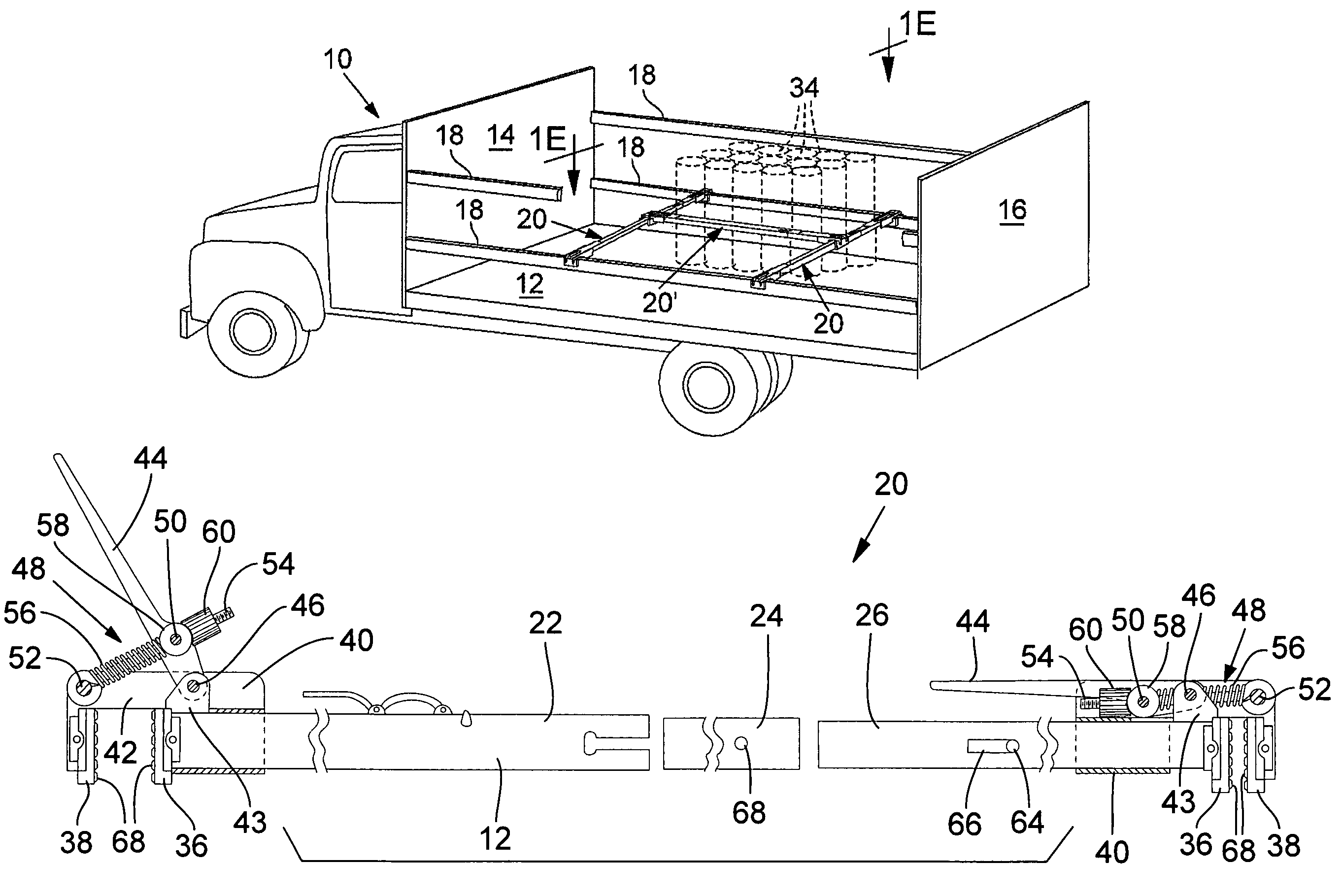
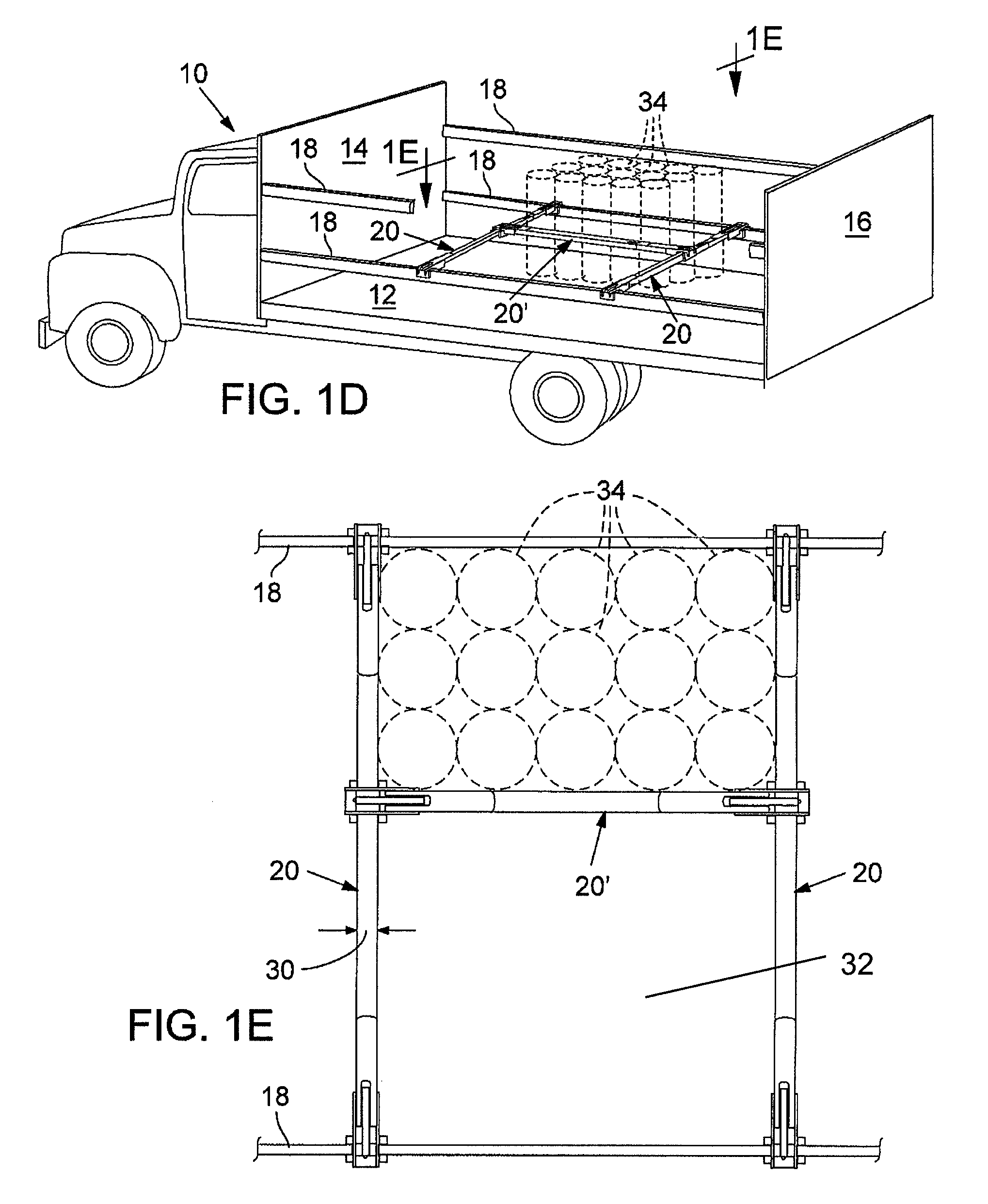
[0012]Reference is first made to FIG. 1D which illustrates a truck 10 having a flat truck bed 12 and front and rear end walls 14 and 16. Extended along the sides are side rails 18. Cargo to be delivered is loaded on the truck bed 12 and confined on the truck bed by the rails 18. The side rails 18 may be of different types i.e. removable or stationary and these may be supported only at the end walls or provided with intermediate support posts. Regardless, such trucks may be used to deliver cargo load segments, the segments being delivered to different locations.

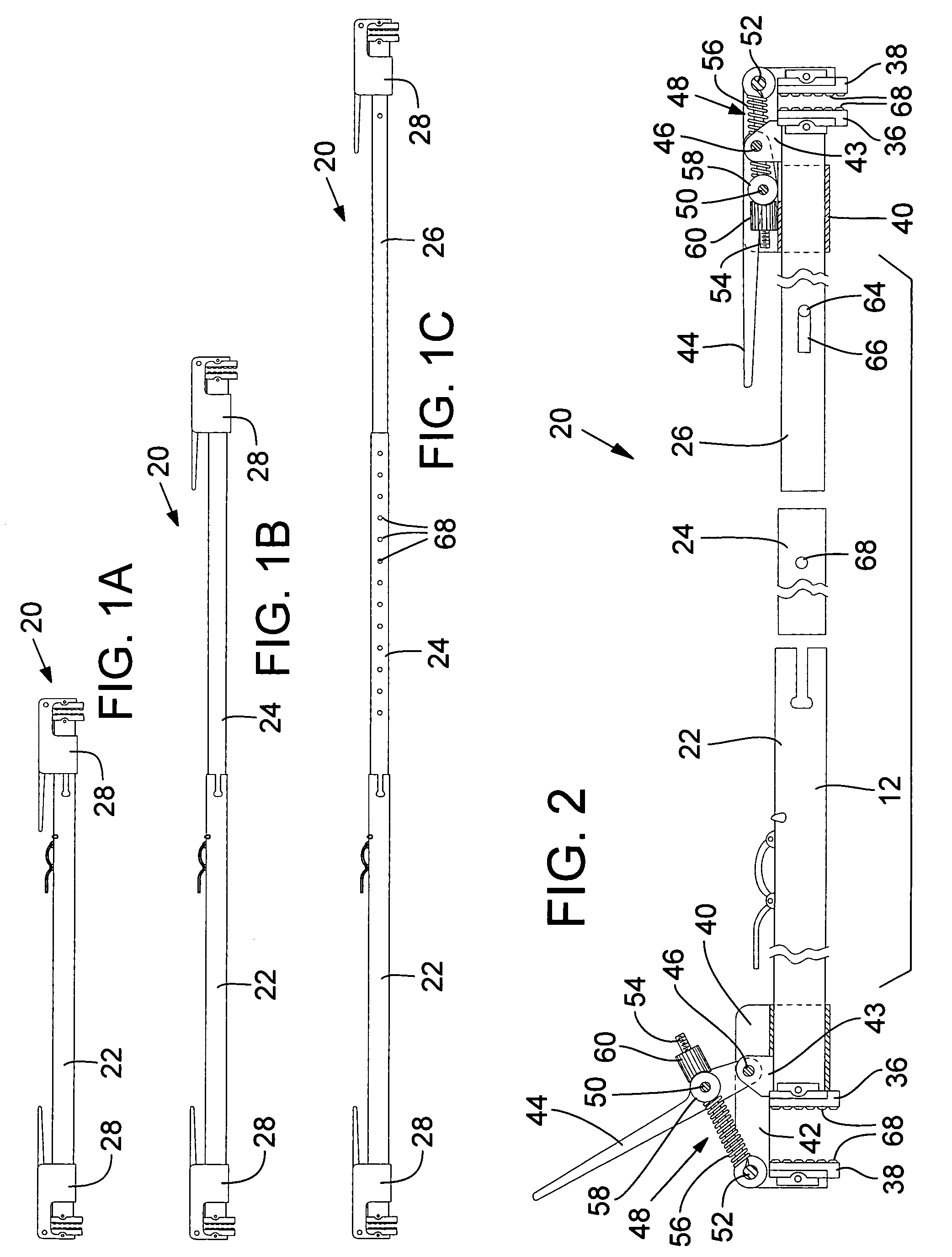
[0013]Typically loads are separated on the truck bed by stabilizing devices that are clamped at the ends to the side rails. Depicted in FIGS. 1D and 1E are the improved stabilizing devices 20 of the present invention. As shown in FIG. 1A through 1C, the stabilizing devices of the present invention are adjustable lengthwise. With particular reference to FIG. 1C and FIG. 2 it will be appreciated that the device 20 is an elongate...


PUM


Abstract

Stabilizing devices having elongate telescoping tube segments and end clamps. The end clamps of certain of the devices are clamped onto side rails of a cargo bed for segmenting a cargo bed length way. The end clamps of other of the devices are clamped to the tube segments of the first devices for segmenting a cargo bed width way. Thus providing stabilization of segmented loads having length and / or width dimensions less than the length and / or width of the cargo bed.

Description

RELATED APPLICATION[0001]The present invention is a Non-Provisional Application of Provisional Application No. 60 / 607,560 filed Sep. 7, 2004 entitled “Cargo Stabilization Device for Vehicles and Trailers with Side Boards,” claims priority to said provisional application, and incorporates its specification in its entirety by reference.FIELD OF THE INVENTION[0002]This invention relates to structures for stabilizing individual segments of a cargo e.g., being delivered to different delivery sites.BACKGROUND OF THE INVENTION[0003]A type of cargo delivery utilizes a truck bed on which different segments of cargo are to be delivered to different sites. The truck bed may include e.g., a flat bed truck provided with side rails that contain the cargo on the truck bed. A removable fabric cover (soft side) may be draped over the sides and raised to allow side removal of the load segments.[0004]A problem occurs when the segments are sequentially unloaded. For example, a first delivery stop may i...

Claims


Application Information

Patent Timeline
Patent Type & Authority Patents(United States)
IPC IPC(8): B60P7/08
CPCB60P7/15
Inventor SCOTT, GARY M.BOEHRER, ROLAND R.
Owner PEERLESS CHAIN COMPANY
Why Eureka
Try Eureka