Multiple-background device for a scanner and calibration device utilizing the same principle

a scanning scanner and multi-background technology, applied in the direction of electrical equipment, pictoral communication, etc., can solve the problems of optical modules not being able to capture a plurality of scan lines, affecting the positioning of optical modules, and affecting the accuracy of scan images using correction values, etc., to achieve low reflectivity area and high reflectivity area

Inactive Publication Date: 2008-08-12
AVISION
View PDF6 Cites 22 Cited by
  • Summary
  • Abstract
  • Description
  • Claims
  • Application Information

AI Technical Summary

Benefits of technology

[0009]The primary objective of the present invention is to provide a multiple-background device for a scanner, in particular a device providing background color alternation function to solve the problem of the black image due to holes or lacerations on an original document.

Problems solved by technology

However, since a moveable optical module is required for the transformation of background, this solution is only applicable to a flatbed scanner in combination with a document feeder, as claimed in U.S. Pat. No. 6,166,394.
The solution disclosed in said US patent requires the position adjustment of the optical module in accordance with the positions of the background and, thus, makes the positioning of the optical module difficult.
If the optical module position corresponding to different background colors changes when performing shading correction, the angles and distances between the optical modules and the original document will be different from those during the scanning process; in result, the scan image using the correction values is defected.
In addition, with the conventional device, the fixed optical module is not capable of capturing a plurality of scan lines, so the result of this shading correction is questionable.
However, the said patent does not solve the problem that the distance between the upper and the lower optical modules may be different from the distance between the original document and the upper optical module.
As a result, the optical path length may be different in the two circumstances and, thus, the accuracy of the shading correction is affected.

Method used


Image

  • Multiple-background device for a scanner and calibration device utilizing the same principle
  • Multiple-background device for a scanner and calibration device utilizing the same principle
  • Multiple-background device for a scanner and calibration device utilizing the same principle

Examples


Embodiment Construction

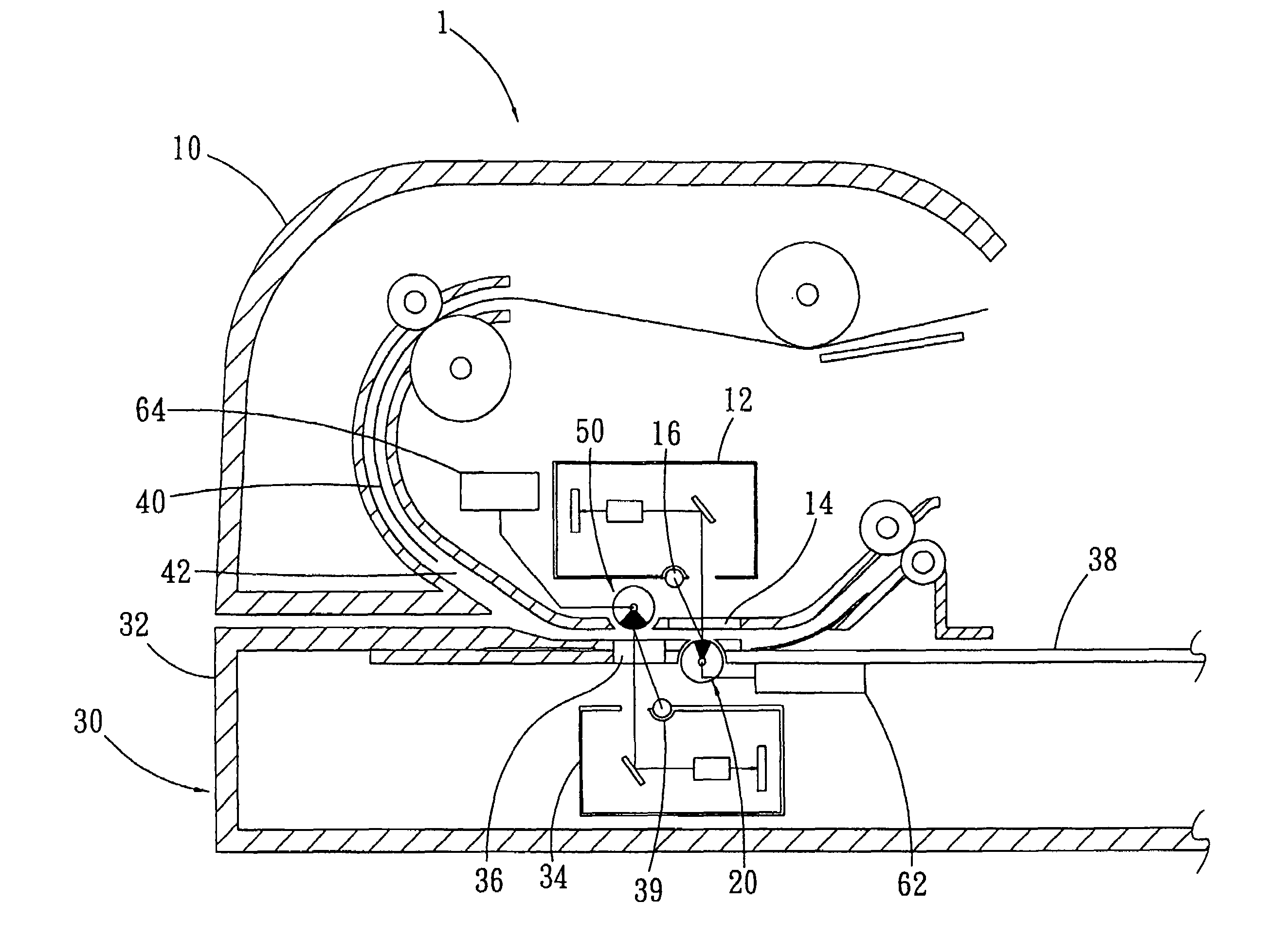
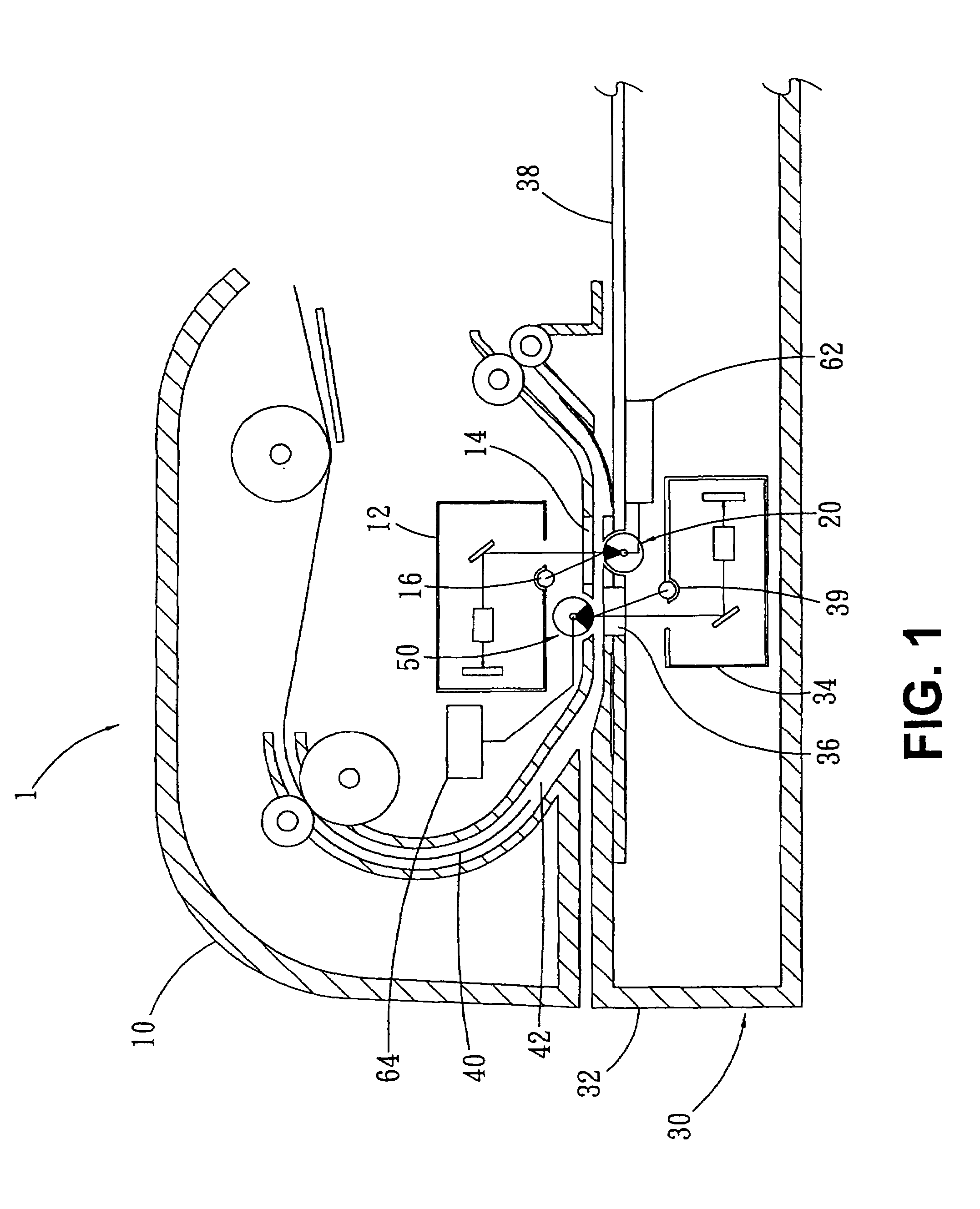
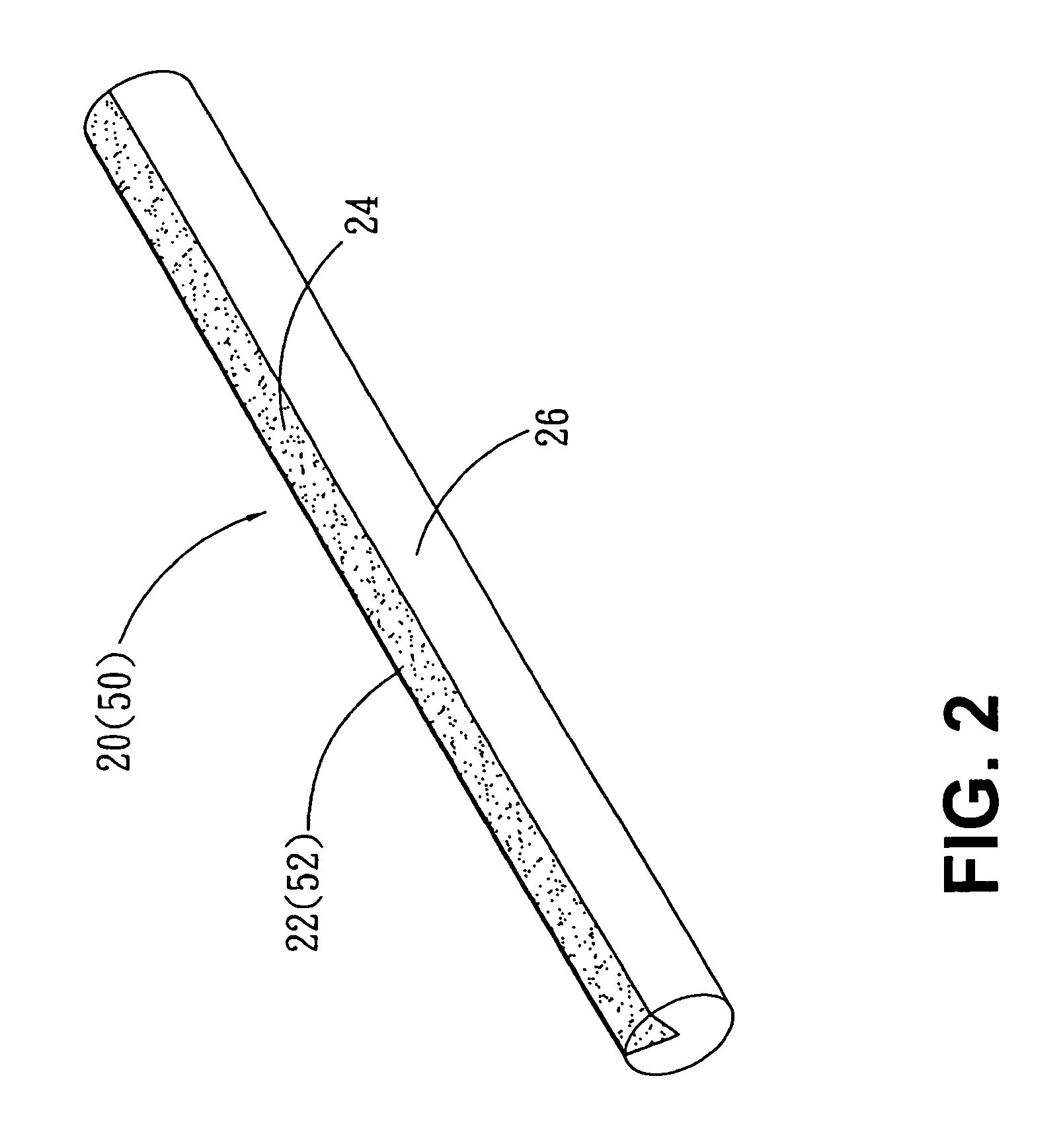
[0021]The embodiment in FIG. 1 shows a scanner 1 with document feeding function as a combination of an automatic document feeder 10 and a flatbed scanner 30. The scanner 1 is capable of duplex scanning. The automatic document feeder (ADF) 10 has a fixed optical module 12 that does not move along with scanning movement. The ADF 10 has a scan window 14 on the bottom thereof and the light emitted from a light source 16 can reach to the scan window 14. Two multiple-background devices 20, 50 are disposed in the scanner 1 and opposite to the optical modules 12, 34 respectively. The multiple-background device 20, for example, is disposed in the flatbed scanner 30 and opposite to the scan window 14. As FIG. 2 shows, the multiple-background 20 has a rotating shaft 22, which has a low reflectivity area 24 and a high reflectivity area 26 on the surface thereof. The low reflectivity area 24 may have a black color and high reflectivity area 26 may have a white color. It is important to note that...


PUM


Abstract

A multiple-background device for a scanner and a calibration device utilizing the same principle are disclosed. The multiple-background device includes a shaft, a low-reflectance portion and a high-reflectance portion are formed along the length of the shaft. Thereby the shaft can provide various background colors, and the optical module can acquire a plurality of scan lines by means of rotating the shaft for image calibration.

Description

BACKGROUND OF THE INVENTION[0001]1. Field of the Invention[0002]This invention relates to a device for alternating scan backgrounds and for facilitating the shading correction of a scanner. In particular, the device provides more than one background color and is capable to alternate the background colors of the scanner. Such, The device provides an optical module of the scanner with scan lines of different shades to adjust the shade value of the optical module.[0003]2. Description of the Prior Art[0004]Conventionally, a flatbed scanner comprises a mobile optical module which move linearly for scanning. When the scanning is in process, the moving optical module captures optical signals of a plurality of scan lines of an original document. An optical sensor of the optical module then produces a scan image based on the acquired scan information.[0005]For an original document with binder holes or lacerations, black image emerge on its scan image at the positions corresponding to the bin...

Claims


Application Information

Patent Timeline
Patent Type & Authority Patents(United States)
IPC IPC(8): H04N1/04H04N1/12H04N1/193H04N1/38H04N1/40
CPCH04N1/121H04N1/125H04N1/2032H04N1/38H04N1/401H04N1/1215H04N2201/044H04N1/193
Inventor WANG, BO-HSIANG
Owner AVISION
Why Eureka
Try Eureka