Method and apparatus for integrating wireless communication and asset location

a technology for asset location and wireless communication, applied in the field of asset location identification of mobile and stationary assets and communication using, can solve the problems of prohibitively high cost per asset, equipment for and installation of a dedicated wireless tag identification system infrastructure, and it is almost unimaginable to have a modern office without a lan, so as to minimize the disruption of both wireless communication system and asset location activities

Active Publication Date: 2008-08-12
RF TECH
View PDF8 Cites 103 Cited by
  • Summary
  • Abstract
  • Description
  • Claims
  • Application Information

AI Technical Summary

Benefits of technology

[0006]In an illustrative embodiment in accordance with one aspect of the invention, a wireless communication system and a wireless tag identification system are configured to operate in a common environment while minimizing disruption of both wireles...

Problems solved by technology

By 1995, it became almost unimaginable to have a modern office without a LAN.
Equipment for and installation of a dedicated wireless tag identification system infrastructure can in some cases be expensive, and when the total number of...

Method used


Image

  • Method and apparatus for integrating wireless communication and asset location
  • Method and apparatus for integrating wireless communication and asset location
  • Method and apparatus for integrating wireless communication and asset location

Examples


Embodiment Construction

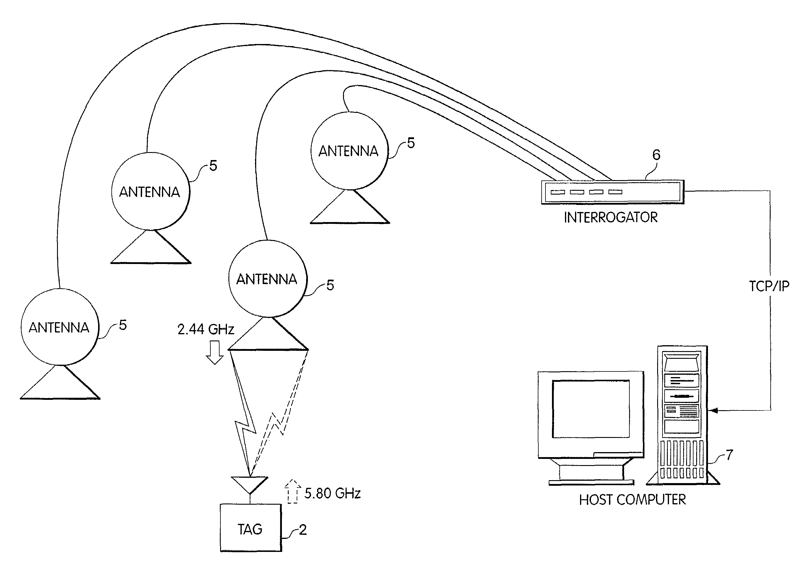
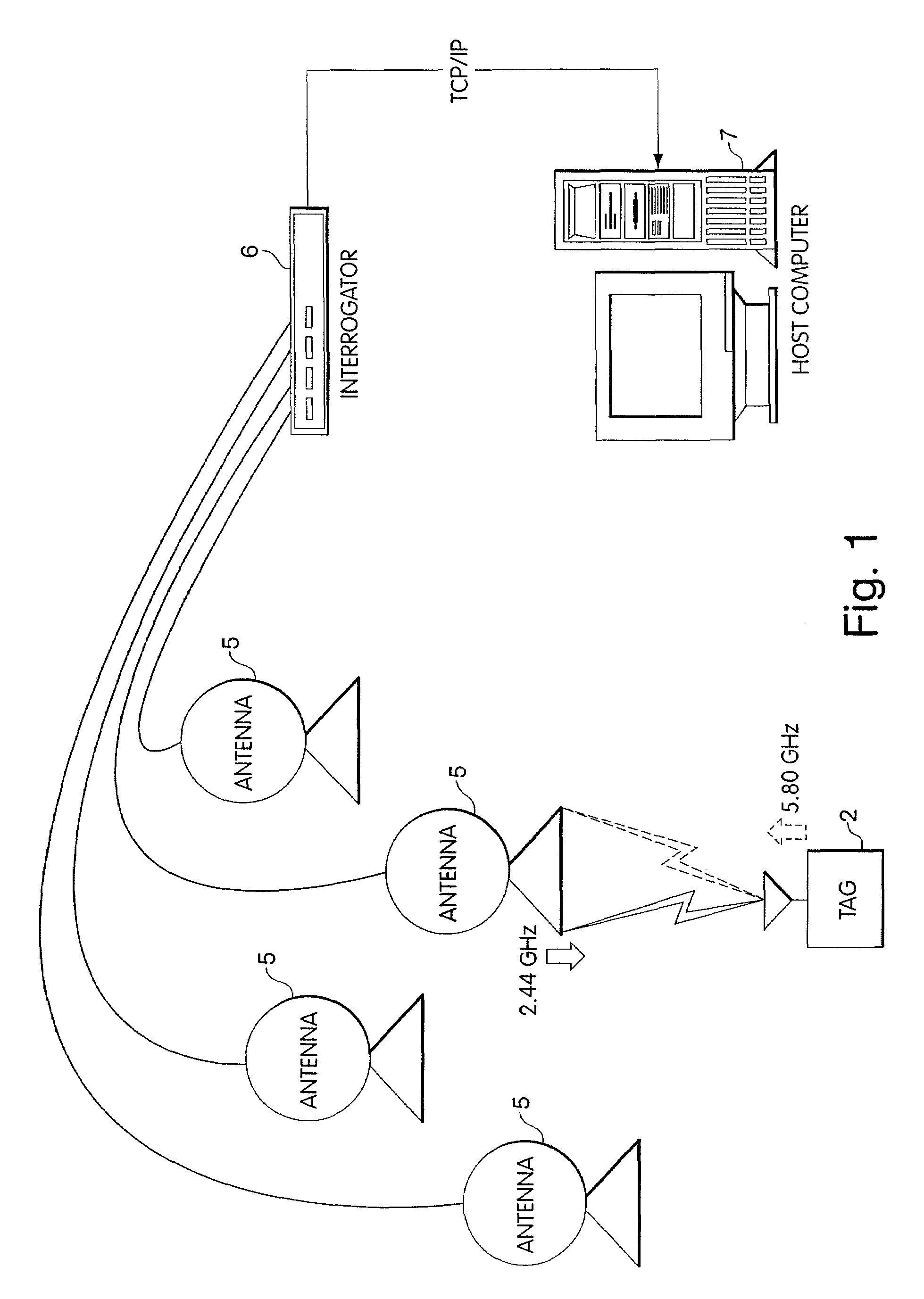
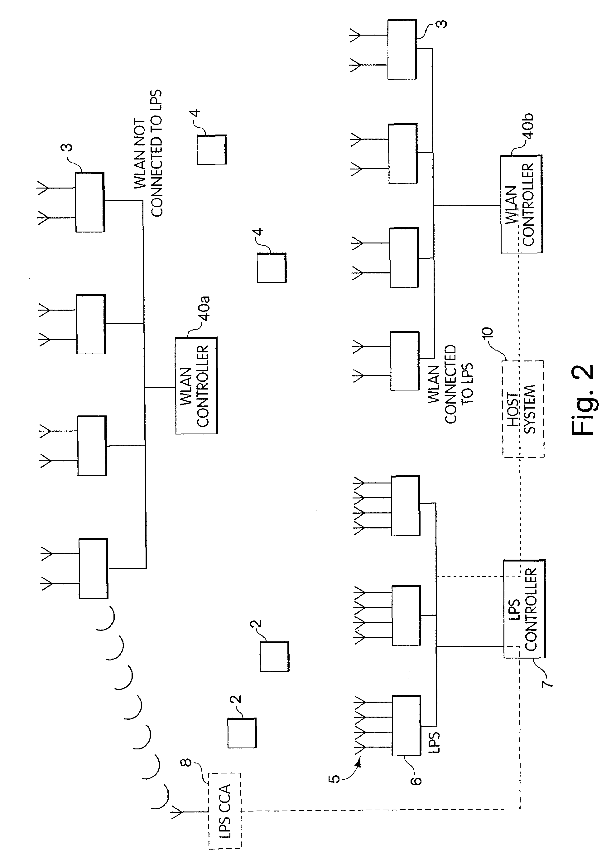
[0035]As discussed briefly above, a Local Positioning System (LPS) is one type of wireless tag identification system that is designed to track the locations of tags as they move through a facility. In some circumstances, users may wish to employ an LPS alongside a wireless communication system, such as an 802.11-based WLAN. In such cases, it may be necessary to coordinate LPS and WLAN traffic in such a way that tags may be continuously tracked without interfering with WLAN communication. Thus, it may be desirable to design a system that would allow LPS and WLAN traffic to coexist without interference, or minimal interference. In addition, users of wireless communication systems may prefer not to install multiple infrastructures. Thus, in order to coordinate LPS and WLAN traffic while decreasing the need to install an additional infrastructure, it may be desirable to design a system with integrated LPS and WLAN capabilities.

[0036]Today, LPSs and WLANs are promoted, justified, and ins...


PUM


Abstract

A method and apparatus to identify tags in a wireless tag identification system. Operation of the wireless tag identification system may be controlled to minimize interference or otherwise improve interoperation with a wireless communication system, such as a wireless local area network (WLAN). For example, the timing and/or power of wireless signals produced by the wireless tag identification system can be controlled to provide sufficient space to the wireless communication system to operate properly. The systems may be tightly integrated, e.g., so that tags may be identified by responding to wireless communications traffic as opposed to special purpose tag search signals. The wireless communications traffic may be modified to enhance tag location resolution.

Description

RELATED APPLICATIONS[0001]The present application is a continuation and claims priority of U.S. patent application Ser. No. 09 / 791,037 to Lanzl et al., filed on Feb. 16, 2001, which is a continuation-in-part of U.S. non-provisional application Ser. Nos. 09 / 517,606, filed Mar. 2, 2000, now U.S. Pat. No. 6,812,824, and 09 / 694,767, filed Oct. 23, 2000, now abandoned, which claims the benefit under 35 U.S.C. §119(e) of U.S. provisional applications 60 / 160,460, filed Oct. 21, 1999, and 60 / 181,848, filed Feb. 11, 2000, which are all hereby incorporated by reference in their entirety. U.S. application Ser. No. 09 / 781,037, and thus this application, also claims the benefit of U.S. provisional application Nos. 60 / 183,193, filed Feb. 17, 2000, 60 / 191,030, filed Mar. 21, 2000, 60 / 216,242, filed Jul. 6, 2000, 60 / 239,593, filed Oct. 11, 2000, and 60 / 247,080, filed Nov. 10, 2000, which are all hereby incorporated by reference in their entirety.FIELD OF THE INVENTION[0002]This invention relates to...

Claims


Application Information

Patent Timeline
IPC IPC(8): H04Q7/00G01S19/42G01S5/02G01S13/76G01S13/78G01S13/79G01S13/87G01S19/11G06K7/00H04L12/28H04W8/00H04W16/14H04W24/10H04W84/12
CPCG01S5/02G01S13/765G01S13/78G01S13/79G01S13/878G06K7/10475H04W16/14G06K7/0008H04W84/12H04W8/005H04W24/10
Inventor STRONG, JONWERB, JAYLANZL, COLIN
Owner RF TECH
Why Eureka
Try Eureka