Endovascular balloon graft

a balloon and endovascular technology, applied in the field of endovascular balloon grafts, can solve the problems of balloon itself obstructing the lumen of the artery, balloons are not suitable for permanent placement, and the device such as angioplasty balloons are unsuitable for permanent placement, so as to facilitate secure placement within the intended portion, minimize disruption or irritation of the lumen, and reduce the risk of injury

Inactive Publication Date: 2006-09-14
MORSI HESHAM
View PDF13 Cites 58 Cited by
  • Summary
  • Abstract
  • Description
  • Claims
  • Application Information

AI Technical Summary

Benefits of technology

[0007] The invention pertains to a method and apparatus for the repair of stenotic vessels utilizing an inflatable device that can open the occlusion with minimized occurrence of residue breaking free within the blood flow, thereby risking injury to another part of the body, while simultaneously creating a smooth interior walled lumen but with an undulating or corrugated outer wall surface to facilitate secure placement within the intended portion of the vessel. The device also can be moved into position while in a collapsed state, thereby minimizing disruption or irritation of the lumen, and subsequently inflated to create a substantially flexible but stiff walled shent capable of contouring to the shape of the lumen without collapse or buckling.

Problems solved by technology

Devices such as angioplasty balloons, however, are unsuitable for permanent placement since the balloon component is fused to the catheter.
Removal of the catheter will cause the collapse of the balloon.
Further, the balloon itself may obstruct the lumen of the artery.
Further, the procedure usually requires two separate steps; the first clearing of the occlusion and, second, the placement of a reinforcing stent with increased risk of embolization and the risk of restenosis.
Devices for treatment of aneurysms may not provide sufficient wall support or, alternatively, have material properties hindering their deployment within the affected portion of a vessel.
Other devices may be subject to dislocation by the mechanics of fluid flow and pressure.
Further, other devices of treating aneurysms, such as coils, are not suitable for certain types of aneurysms, e.g., wide neck or fusiform aneurysms.
They may also be subject to incomplete olbitration of the aneurysm or coil compaction which may result in re-growth of the aneurysm and future rupture.

Method used


Image

  • Endovascular balloon graft
  • Endovascular balloon graft
  • Endovascular balloon graft

Examples


Embodiment Construction

[0024] The above general description and the following detailed description are merely illustrative of the subject invention and additional modes, advantages and particulars of this invention will be readily suggested to those skilled in the art without departing from the spirit and scope of the invention.

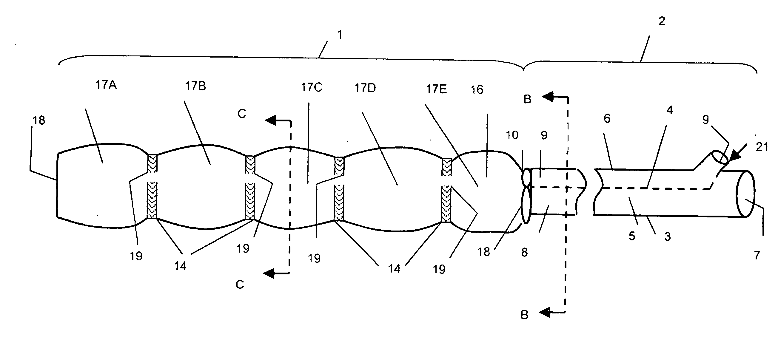
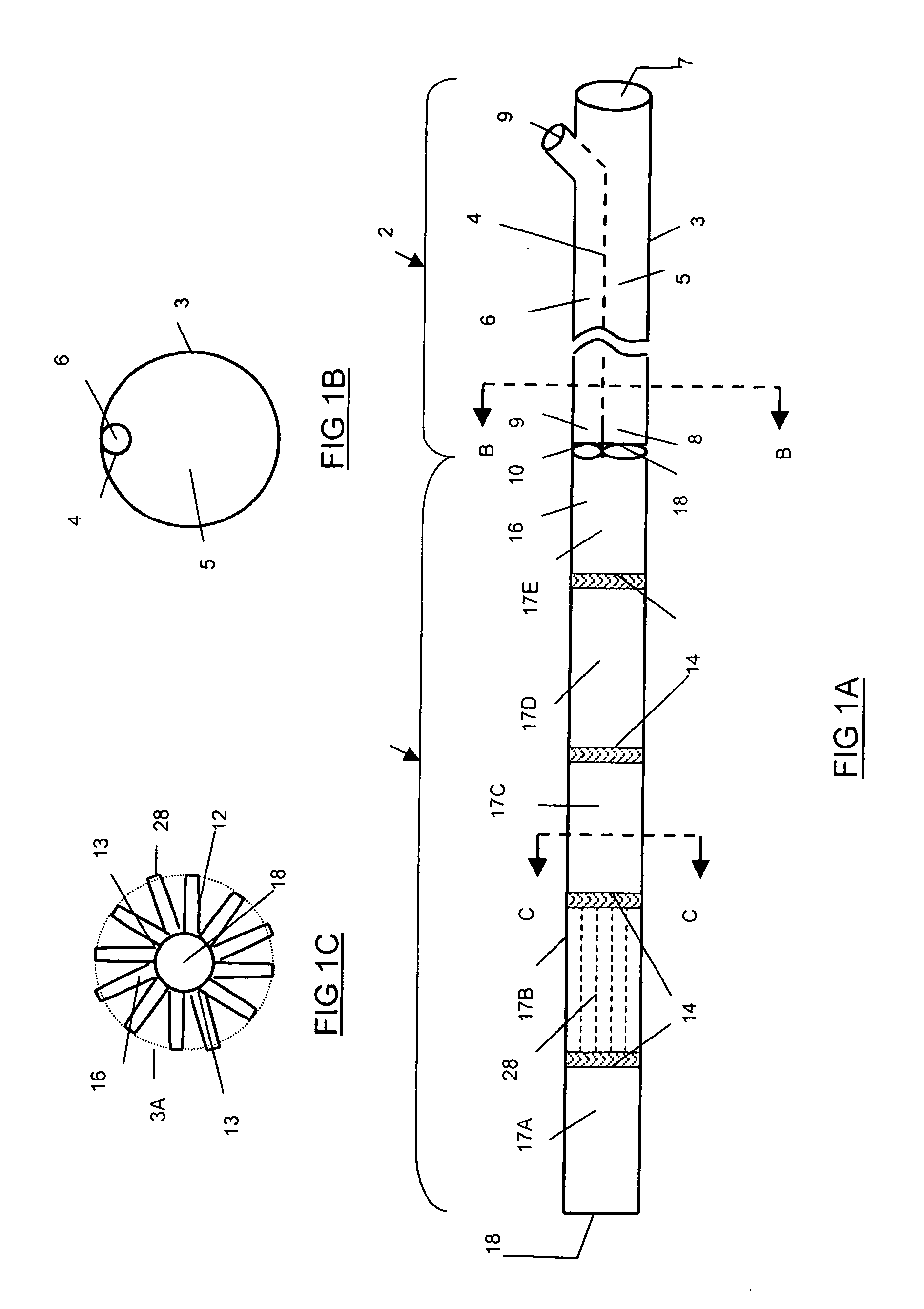
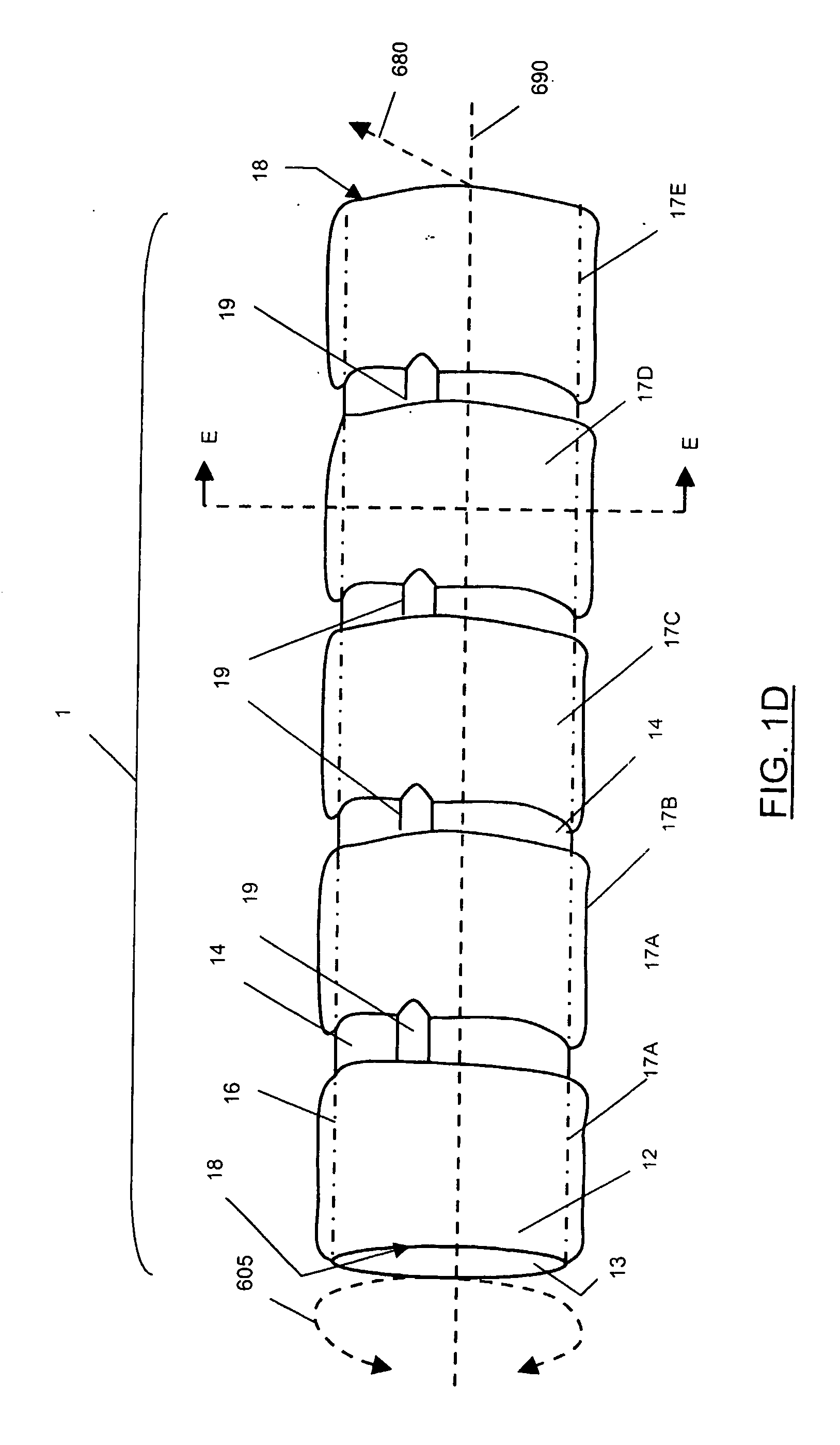
[0025]FIG. 1A illustrates the system of the invention, being composed of a distal segment 1, which represents the expandable graft and a proximal segment 2, which represents the delivery catheter. The catheter 2 has a double lumen shaft 3. FIG. 1B illustrates a cross sectional schematic of the catheter at a vector arrow BB in FIG. 1A. As shown in FIGS. 1A and 1B, the larger lumen 5 has an aperture proximally 7, and opens distally 8 into the lumen 18 of the distal segment that provides an artificial flow path for the body lumen. Through this lumen, a guiding wire (not shown) can be inserted to facilitate proper positioning of the graft at the desired location in the cerebral or per...


PUM


Abstract

A method and apparatus for repair of stenotic and aneurysmic vessels utilizing in situ deployment of an inflatable tubular shaped device (1) having a longitudinally oriented annulus (17). When inflated, the size and rigidity of the device (1) is increased, thereby providing supplemental strength to the vessel wall and a lumen (8) for the passage of fluid.

Description

CROSS REFERENCE TO RELATED APPLICATION [0001] This application claims the benefit of and priority to U.S. Provisional Application No. 60 / 437,092 entitled “Morsi Balloon Graft” and filed Dec. 30, 2002BACKGROUND OF INVENTION [0002] 1. Field of Use [0003] The invention pertains to a graft design that combines the minimal size and increased flexibility in its deliverable form which allows for successful navigation of torturous, stenotic blood vessels, aneurysms and other body passages with an in situ increase in size and rigidity, thus improving upon the current covered stent in treatment of various diseases such as atherosclerosis and aneurysms. The invention can be utilized in both the cerebral or peripheral circulatory system. [0004] 2. Prior Art [0005] Inflatable devices for opening stenotic blood vessels are known. Devices such as angioplasty balloons, however, are unsuitable for permanent placement since the balloon component is fused to the catheter. Removal of the catheter will ...

Claims


Application Information

Patent Timeline
Patent Type & Authority Applications(United States)
IPC IPC(8): A61F2/06A61F2/82
CPCA61F2/07A61F2/82A61F2250/0003A61F2/89A61F2230/005Y10S623/903
Inventor MORSI, HESHAM
Owner MORSI HESHAM
Why Eureka
Try Eureka