Cantilever mixed type dry vacuum pump

A dry vacuum pump and hybrid technology, applied in the direction of rotary piston/swing piston pump components, rotary piston pumps, pumps, etc., can solve problems such as unguaranteed, performance degradation of screw pumps, and dead angles in channels, etc., to achieve Reasonable design and compact structure

Active Publication Date: 2021-06-29
上海樊容工业技术中心
View PDF6 Cites 2 Cited by
  • Summary
  • Abstract
  • Description
  • Claims
  • Application Information

AI Technical Summary

Problems solved by technology

But the main disadvantage is: because the air flow channel flows radially along the shaft, the air flow cannot effectively flow along the axial direction after the multi-stage Roots are connected in series, and it needs to be bent multiple times to achieve it, resulting in a complex structure. The channel must have defects such as dead ends
At the same time, if the single-stage Roots pump is operated alone, the ultimate vacuum is very poor and the energy consumption is high. When dealing with high vacuum applications, it is necessary to configure a backing pump to operate properly.
The characteristic of the screw pump is that the gas moves helically along the axial direction, and multi-stage compression is realized through multiple helical meshes, so it can be directly used for higher vacuum applications without the traction of the backing pump, but the disadvantage is that : The volume ratio of the screw is low, and the pumping capacity produced by the pump cavity of the same diameter is far lower than that of the Roots rotor. At the same time, the meshing and sealing of the rotor is poor, and its surface wear and corrosion have a great impact on its performance. At the same time, the exhaust port The air flow will directly impact the bearings and gears, so when the screw pump is dealing with corrosive gases, the damage rate of the pump is very high
[0005]However, the structure of the original multi-stage pump has many deficiencies and hidden dangers in actual operation. The gap of the rotor needs to be enlarged, and the shaft sleeve also needs to be enlarged to avoid the phenomenon of jamming, so that even if it is five-stage, it cannot guarantee a high degree of vacuum
At the same time, it is difficult to clean the liquid and accumulated dust at the low point of the pump body, and the exhaust pipe is relatively narrow, resulting in exhaust noise and panting, which are difficult to improve. The most important thing is to use five-stage Roots. In rough vacuum, at this time Through continuous compression, the gas pressure has exceeded the atmospheric pressure in the third stage or even the second stage, but the latter stages are still compressing, resulting in high shaft power, which reduces energy efficiency and economy
[0006]Original dry vacuum pumps, such as screw pumps and multi-stage pumps, etc., all have built-in gas communication pipes. Slime and process media that can carbonize, solidify, polymerize, etc., these media will inevitably accumulate in the low points of the equipment, even with solvent washing and nitrogen purging, it is difficult to remove, and these substances will aggravate the damage to the dry vacuum pump For example, dust and media that can carbonize, solidify, aggregate, etc. will grind the screw rotor, and will soon wear the sealing surface of the screw rotor, resulting in a significant decline in the performance of the screw pump; for multi-stage pumps, although these substances The wear effect on the Roots rotor is much smaller than that on the screw, but there must be a low point in its structure, and the accumulation of these media at the low point will eventually lead to the blockage of the channel. Like the screw pump, it will inevitably If the rotor is stuck, only by dismantling the whole pump and pulling out the rotor can the internal adherents and other residual process media be thoroughly cleaned, which is very inconvenient for the on-site users. Repair tools and experience, but also necessary access space and repair time

Method used


Image

  • Cantilever mixed type dry vacuum pump
  • Cantilever mixed type dry vacuum pump
  • Cantilever mixed type dry vacuum pump

Examples


Embodiment Construction

[0036] Embodiments of the technical solutions of the present invention will be described in detail below in conjunction with the accompanying drawings. The following examples are only used to illustrate the technical solutions of the present invention more clearly, and therefore are only examples, rather than limiting the protection scope of the present invention.

[0037] It should be noted that, unless otherwise specified, the technical terms or scientific terms used in this application shall have the usual meanings understood by those skilled in the art to which the present invention belongs.

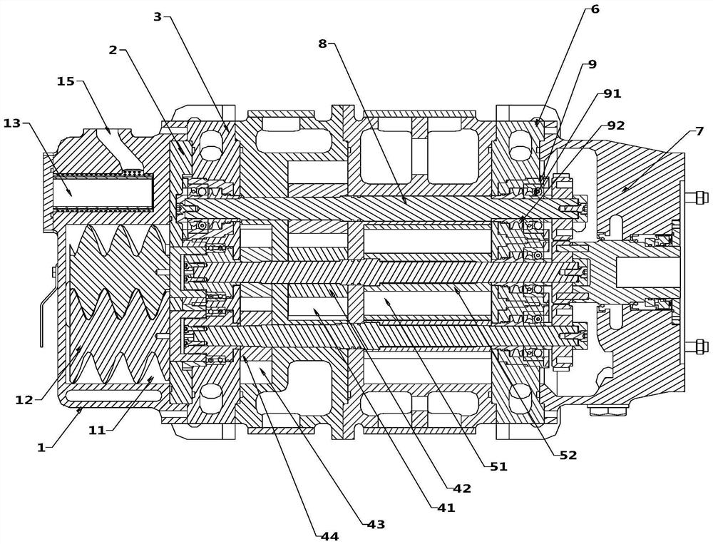
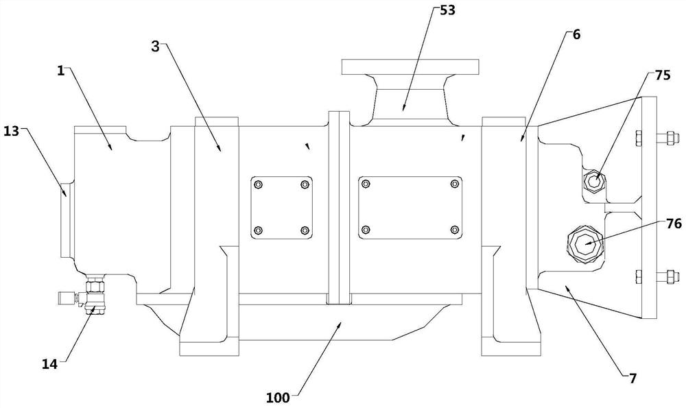
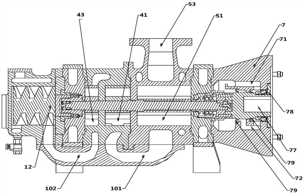
[0038] This embodiment provides a cantilever hybrid dry vacuum pump, such as Figure 1 to Figure 3 As shown, it includes a cantilever shell 1, a cantilever rotor cover 2, a cantilever end cover 3, a non-cantilever body, a gear end cover 6 and a sealed motor connection seat 7 arranged horizontally and connected in sequence. In this embodiment, the non-cantilever The body includes thr...


PUM


Abstract

The invention discloses a cantilever mixed type dry vacuum pump which comprises a cantilever cavity and a non-cantilever body, the non-cantilever body is a pump cavity set formed by connecting a plurality of pump cavities in series, and any adjacent parts of the cantilever cavity and the non-cantilever body are positioned in an embedded mode. Each pump cavity in the non-cantilever body and the cantilever cavity are connected in series through a gas circuit, a bottom connecting piece is arranged below the non-cantilever body and the cantilever cavity to serve as an independent gas connecting part, and the bottom connecting piece is detachably connected with the cantilever cavity and the non-cantilever body. The cantilever mixed type dry vacuum pump is reasonable in design and compact in structure. The bottom connecting piece can reserve enough stacking space for sediments and can be freely disassembled, cleaned, overhauled, maintained and replaced without blocking an airflow channel. Positioning pin holes do not need to be formed in the side faces of the adjacent parts for positioning, and therefore the defects that an airflow channel arranged in a pump cavity of a traditional dry vacuum pump is narrow, washing and maintenance cannot be carried out, and faults are caused are overcome.

Description

technical field [0001] The invention relates to the technical field of dry vacuum pumps, in particular to a cantilever hybrid dry vacuum pump. Background technique [0002] The existing dry vacuum pumps are mainly Roots pumps and screw pumps, and most Roots pumps and screw pumps on the market are two-shaft, and their pump bodies are suitable for placement and can only accommodate two intermeshing pumps. Roots rotor or screw structure. [0003] Among them, the characteristics of the rotor of the Roots pump are: the gas moves up and down along the radial direction of the shaft. When used as a booster pump with relatively high vacuum, the volume ratio is high, the pumping capacity is large, and the rotor meshing and sealing performance is high. Wear and corrosion have little effect on performance, and the airflow will not directly impact the bearings and gears. But the main disadvantage is: because the air flow channel flows radially along the shaft, the air flow cannot effec...

Claims


Application Information

Patent Timeline
Patent Type & Authority Applications(China)
IPC IPC(8): F04C23/00F04C18/12F04C18/16F04C25/02F04C27/00F04C29/02
CPCF04C23/005F04C18/12F04C18/16F04C25/02F04C29/02F04C27/00
Inventor 林峰跃
Owner 上海樊容工业技术中心
Why Eureka
Try Eureka