Conjoined electrical cords for an examination table

a technology of electrical cords and examination tables, which is applied in the field of examination tables, can solve the problems of additional manufacturing costs, complexity, and leakage current in the outlet of tables so equipped, and achieve the effect of less expensiv

Inactive Publication Date: 2008-08-19
MIDMARK
View PDF7 Cites 15 Cited by
  • Summary
  • Abstract
  • Description
  • Claims
  • Application Information

AI Technical Summary

Benefits of technology

[0004]Embodiments of the present invention address the problems of the prior art by isolating the accessory receptacle from the table chassis and running a second power cord complete with a ground from the accessory receptacle to an electrical power source. Another cord that may be grounded to the table chassis may be used to power the remaining electrical components of the examination table. The two cords may be connected together with molded loops or other conjoining connectors to keep the cords together. The conjoined cord feature is simpler and less expensive than isolation transformer approaches, while providing the necessary patient protection from leakage current.

Problems solved by technology

Despite their convenience and utility, outlets on tables may be a source of leakage current.
Despite their effectiveness, however, such isolation transformers add complexity and additional manufacturing costs to tables so equipped.

Method used


Image

  • Conjoined electrical cords for an examination table
  • Conjoined electrical cords for an examination table
  • Conjoined electrical cords for an examination table

Examples


Embodiment Construction

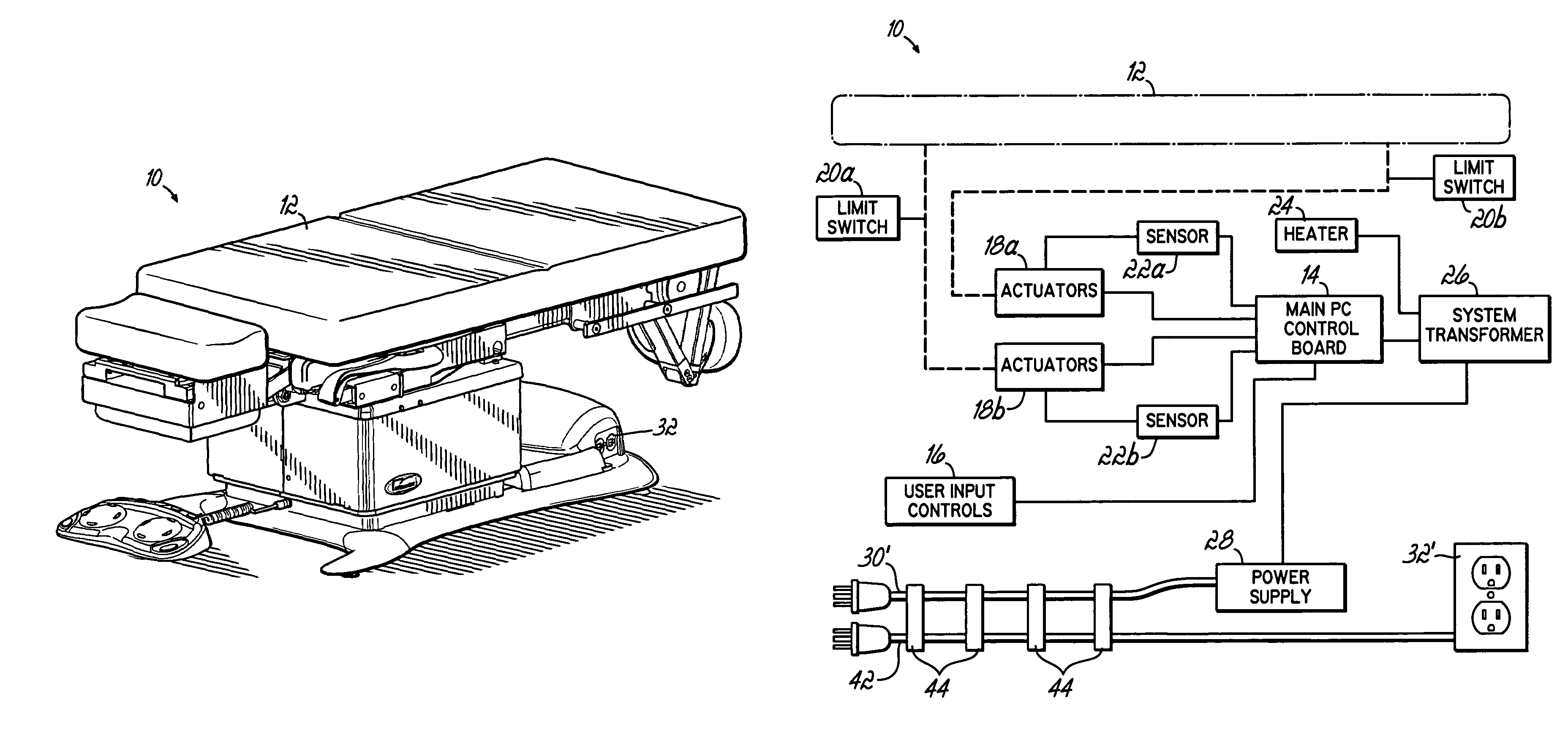
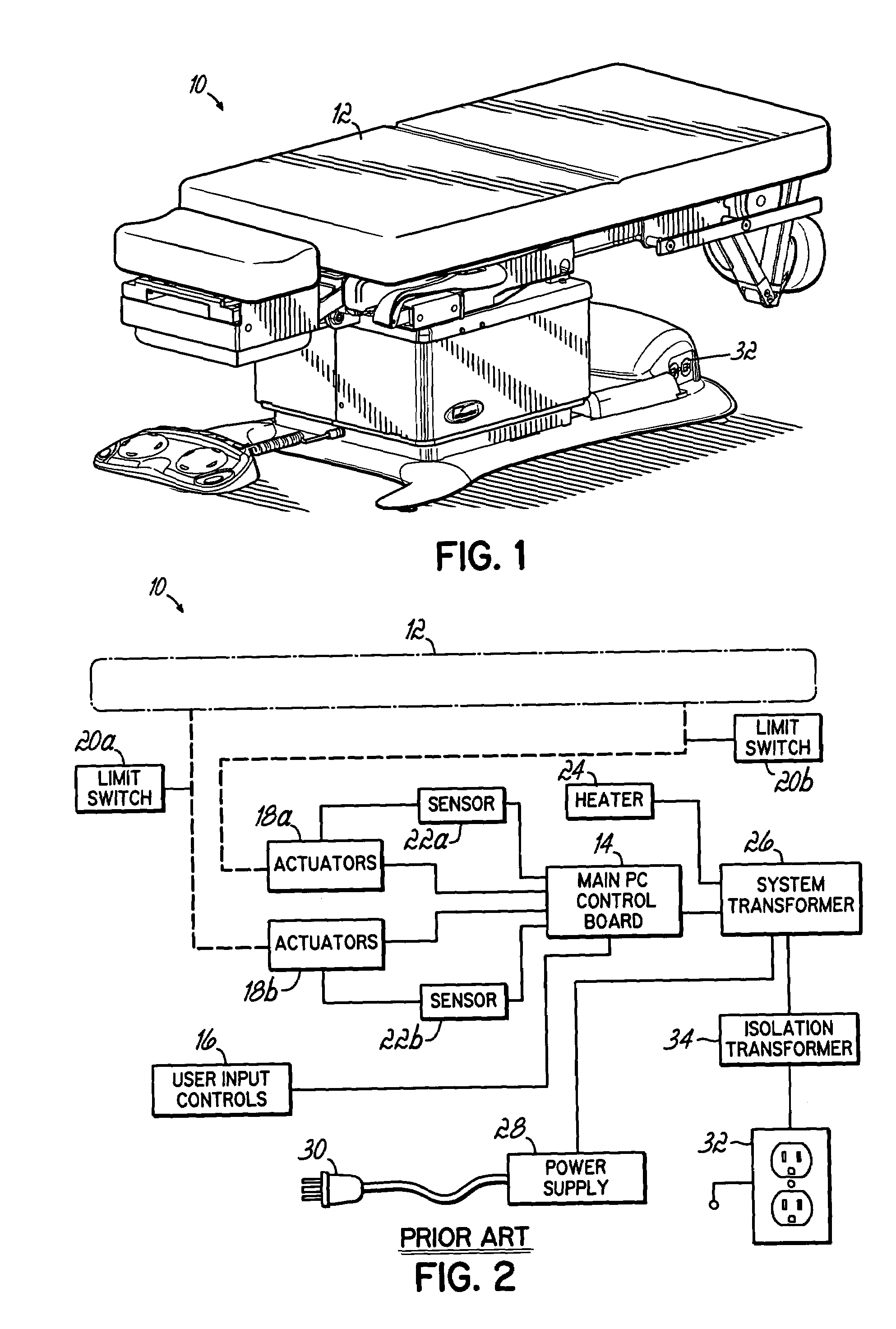
[0012]FIG. 1 is perspective view of an examination table 10 with an actuatable patient surface 12. FIG. 2 shows a conventional block diagram for electrical components of an examination table 10, such as is shown in FIG. 1. To achieve the actuation of the surface, the examination table 10 contains a plurality of actuators 18a, 18b that adjust the patient surface(s). The actuators 18a, 18b are connected to a main PC control board 14 of the examination table 10. The actuators 18a, 18b are monitored by a plurality of position sensors 22a, 22b. Movements of the actuators 18a, 18b are limited by a plurality of limit switches 20a, 20b. The limit switches 20a, 20b and position sensors 22a, 22b are also connected to the main PC control board 14. The actuators 18a, 18b are controlled by user input controls 16 that are either operated by hand or by foot. The user input controls 16 are connected to the main PC control board 14. The main PC control board 14 is connected to the secondary side of ...


PUM


Abstract

An examination table including an actuatable patient surface comprising electronic components configured to adjust said examination table, a power supply to provide power to said electronic components and an electric power receptacle mounted to said examination table. A first electrical power cord is configured to connect said power supply to a first power source and a second electrical power cord is configured to connect said electric power receptacle to a second power source, wherein the electric power receptacle is grounded through said second electrical power cord. A conjoining connector is configured to attach the first electrical power cord to the second electrical power cord along the length of the cords.

Description

FIELD OF THE INVENTION[0001]The present invention generally relates to examination tables and, more particularly, to shielding a patient occupying an examination table from leakage current.BACKGROUND OF THE INVENTION[0002]Medical examination tables are conventionally provided with various electrical components. One such common component includes one or more electrical outlets for plugging in accessories. Despite their convenience and utility, outlets on tables may be a source of leakage current. Leakage current is the current that can flow through a protective ground conductor to ground. In the absence of a grounding connection, leakage current could seek ground through a path that includes a patient's body.[0003]This undesirable phenomenon is addressed conventionally by including an isolation transformer on the power supply to an accessory receptacle. The ground from the accessory receptacle is typically tied to the chassis of the table. Arranged as such, leakage current from the a...

Claims


Application Information

Patent Timeline
Patent Type & Authority Patents(United States)
IPC IPC(8): A61G7/002A61G13/02A61G7/05A61G13/10
CPCA61G13/02A61G13/0018
Inventor HYRE, RODNEY L.EVERS, RANDALL H.
Owner MIDMARK
Why Eureka
Try Eureka