Supercharge Your Innovation With Domain-Expert AI Agents!

Wide view field area camera apparatus and monitoring system

Inactive Publication Date: 2008-08-19
SHARP KK +1
View PDF20 Cites 15 Cited by
  • Summary
  • Abstract
  • Description
  • Claims
  • Application Information

AI Technical Summary

Benefits of technology

[0042]Thus, the invention described herein makes possible the advantage of providing: (1) a camera apparatus configured in a simple and fixed manner so as to reduce a blind area created within a widely ranging image area and, in particular, a blind area in the vicinity of a direction vertically downward from the camera apparatus, when monitoring a small place, while simplifying adjustments during installation; and (2) a monitoring system including the same camera apparatus.

Problems solved by technology

In many cases, automated teller machines (ATM) for automatically paying / receiving money are installed in a relatively small area within a bank or the like, where money is handled, and therefore there is a high possibility that a criminal activity such as larceny might occur.
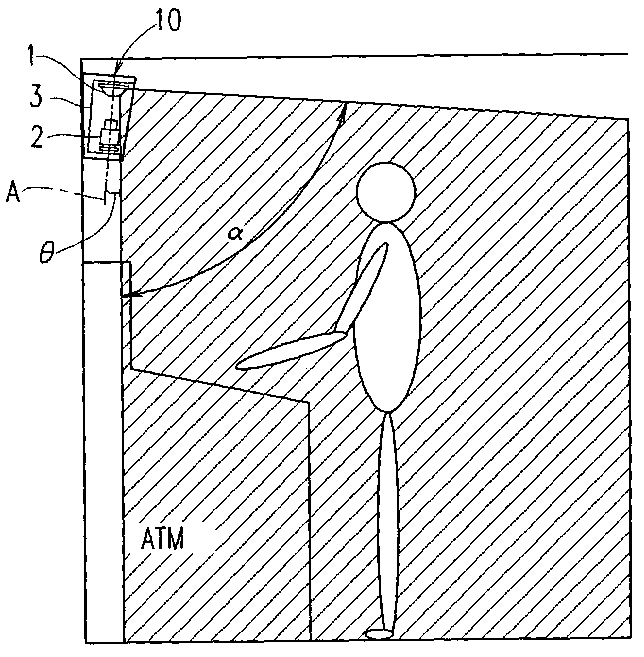
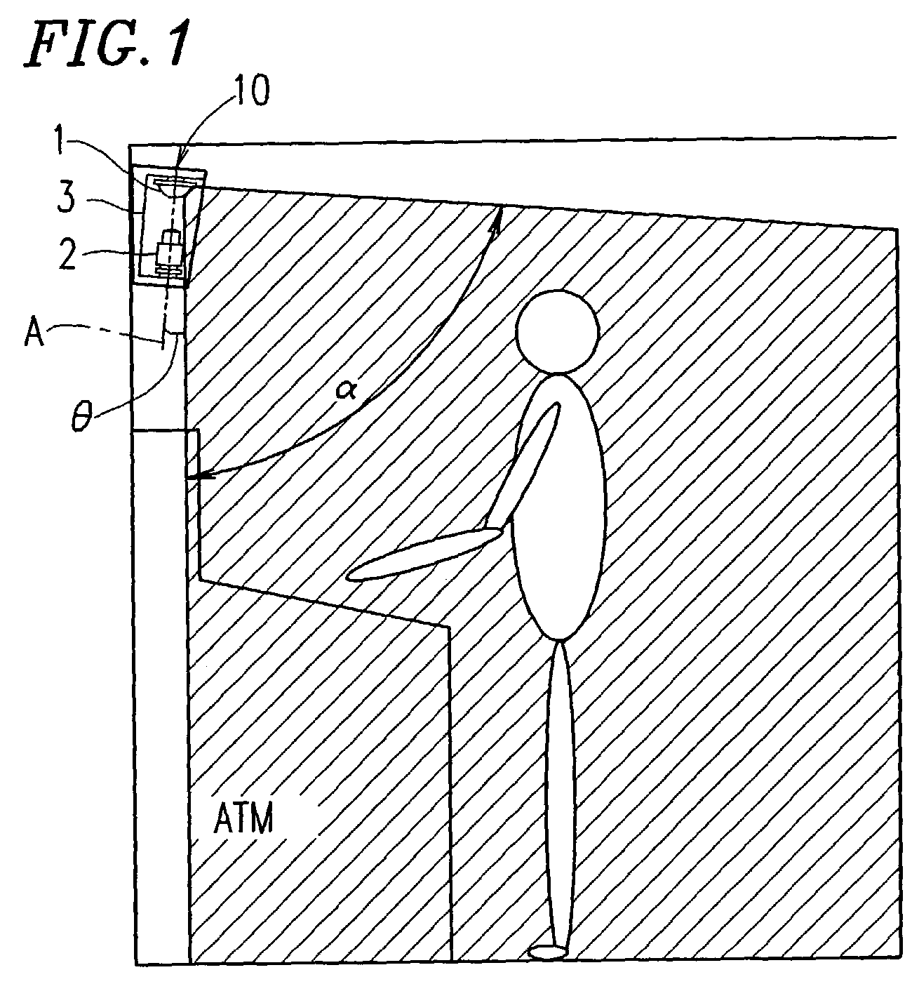
However, in many cases, ATMs are installed in a relatively small area, and therefore a target for monitoring cannot be sufficiently distanced from the location where a monitoring camera is installed.
Therefore, there is a possibility that a view field area for an image obtained by the monitoring camera might be limited.
In particular, a monitoring camera using an industrial television (ITV) camera has a problem that an angle α of view which enables monitoring is predetermined by an optical system of the monitoring camera, and therefore part of the target for monitoring is located out of an area defined by the angle of view, i.e., the target for monitoring is partially located in a blind area.
Such a blind area cannot be monitored, i.e., an operation panel of the ATM cannot be monitored.
On the other hand, although not shown in the figures, when an installation angle of the monitoring camera is adjusted so as to monitor the operation panel of the ATM, it is not possible to obtain an image of a sufficiently widely ranging area for monitoring the ATM operator.
However, in such a case, it is necessary to provide, in addition to the ITV camera, the turntable for turning the ITV camera and the driving device or the like for pivotably driving the turntable, and therefore the configuration of the monitoring system becomes complicated.
However, in such a case, there is a problem in that a large wide-angle lens causes the ITV camera to be increased in size.
Further, the ITV camera becomes expensive by the cost of the wide-angle lens.
Specifically, it is necessary to adjust an installation angle, etc., of the ITV camera while viewing an image displayed on a monitor during the installation of the ITV camera, and this is a complicated and time-consuming task.
This increases the size of the imaging section, and thus an area located in a direction vertically downward from the camera apparatus, where obtaining an image is not possible, is also increased.
As a matter of course, the device is restricted in its design.
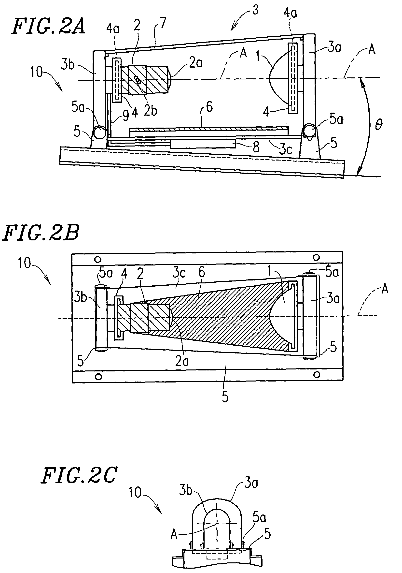
Further still, the panoramic imaging apparatus described in Japanese Laid-Open Patent Publication No. 2000-206635 does not have a mechanism for maintaining the camera in the state of being opposed to a reflecting surface of the hyperboloidal convex mirror.
Although a positional relationship between the hyperboloidal convex mirror and the camera is important in order to obtain a clear and high resolution image, it is difficult to separately install the hyperboloidal convex mirror and the camera in a place where an image obtaining operation is performed, such that the positional relationship between the hyperboloidal convex mirror and the camera is adjusted so as to bring the camera into focus.

Method used


Image

  • Wide view field area camera apparatus and monitoring system
  • Wide view field area camera apparatus and monitoring system
  • Wide view field area camera apparatus and monitoring system

Examples


Embodiment Construction

[0053]Hereinafter, embodiments of the present invention will be described with respect to a camera apparatus and with reference to the accompanying drawings.

[0054]FIG. 1 is a side view showing an example where a camera apparatus 10 according to the present invention is installed on a wall above an ATM installed in a closed area within a bank or the like so as to monitor the place where the ATM is installed.

[0055]As shown in FIG. 1, the camera apparatus 10 according to the present invention includes a mirror (a curved mirror) 1 having a shape of a body of rotation (hereinafter, referred to as the “rotation body mirror 1”) for projecting image light representing an image of a widely ranging area toward a prescribed direction and an imaging section 2 for obtaining, as an image, the image light projected by the rotation body mirror 1. The rotation body mirror 1 and the imaging section 2 are held by a holding member 3 having a box-like structure in which three side surfaces are open, suc...


PUM


Abstract

A camera apparatus of the present invention comprises: an optical system for projecting image light representing an image of a wide view field area toward a prescribed direction; an imaging section for obtaining, as an image, the image light projected by the optical system; and a holding member for integrally holding the optical system and the imaging section in a state where the curved mirror and the imaging section are opposed to each other.

Description

BACKGROUND OF THE INVENTION[0001]1. Field of the Invention[0002]The present invention relates to a camera apparatus and a monitoring system, and more particularly to a camera apparatus, which includes a curved mirror reflecting image light representing an image of a wide view field area toward a prescribed direction and an imaging section for obtaining, as an image, the image light reflected by the curved mirror, capable of obtaining an image of a wide view field area and a system including the same camera apparatus.[0003]2. Description of the Related Art[0004]In many cases, automated teller machines (ATM) for automatically paying / receiving money are installed in a relatively small area within a bank or the like, where money is handled, and therefore there is a high possibility that a criminal activity such as larceny might occur. Accordingly, a place where an ATM is installed is required to be monitored at all times using a monitoring camera.[0005]When monitoring an ATM, it is nece...

Claims


Application Information

Patent Timeline
IPC IPC(8): H04N7/18H04N9/47H04N5/238G08B25/00H04N5/225H04N5/232H04N5/262
CPCH04N5/2628H04N5/2259H04N23/58
Inventor KAKOU, NORITOSHIMISAWA, MASAHIRO
Owner SHARP KK
Features
  • R&D
  • Intellectual Property
  • Life Sciences
  • Materials
  • Tech Scout
  • Unparalleled Data Quality
  • Higher Quality Content
  • 60% Fewer Hallucinations
Learn More