Method for improving the seismic resolution

a seismic resolution and seismic technology, applied in the field of seismic resolution improvement, can solve the problem that the apparent dominant frequency cannot be sufficient, and achieve the effect of improving seismic resolution, enhancing apparent dominant frequency, and improving seismic resolution

Active Publication Date: 2008-08-19
PETROCHINA CO LTD +1
View PDF12 Cites 16 Cited by
  • Summary
  • Abstract
  • Description
  • Claims
  • Application Information

AI Technical Summary

Benefits of technology

[0004]In order to overcome the shortcomings of the prior art, that the apparent dominant frequency of the seismic wave cannot be sufficient for the need of recognizing the thin layer in the present seismic exploration, since it can only be improved to around 60 Hz, the method of the present invention is provided for improving the seismic resolution. This method of improving the seismic resolution can enhance the apparent dominant frequency of the seismic to 200 Hz and higher, improve the vertical seismic resolution, and resolve the problem that it is difficult to recognize the thin layer in the present seismic exploration.
[0005]The starting point of the conception in accordance with the present invention is to recover the seismic wave received by the ground seismic data to the seismic wave produced by the small dose of dynamite in the high-velocity layer and the seismic wave received in the high-velocity layer that is below the low-velocity layer, compensate the influence to the seismic wave caused by the attenuation and the wave dispersion of the seismic wave at the near-surface, therefore, envisage the subject of improving the vertical seismic resolution.
[0008](2) separating the ghost wave of xi(t) from the high-velocity layer by using a method of the vertical seismic profiling, improving the signal-to-noise ratio (SNR) of the seismic record of the direct wave xn(t) at the high-velocity layer by using a uphole stacking of the vertical seismic profiling, and providing the static correction to the x0(t) seismic record;
[0020]The huge attenuation and the wave dispersion of the seismic wave at the near-surface of the ground may be compensated after this method is administered. The duration of the seismic wavelet is shortened greatly. The apparent dominant frequency of the conventional SX seismic profiling g(t) reaches 240 Hz, which is shown in FIG. 2. However, the apparent dominant frequency of the conventional SX is only 55 Hz, which is shown in FIG. 3. The data shown in FIG. 2 adapts to the prior data of the exploratory well better. Therefore, this method can improve the resolution greatly, and resolve the problem that it is difficult to recognize the thin layer by the present seismic exploration. When this method is processing, the structural characteristics on the profiling, such as fault, crease etc., are clear, the phenomena of the lithologic sequence stratigraphy, such as superior, progradation, watercourse etc., are evident, and it has an importance to the seismic reservoir forecasting, the petroleum detection of the seismic, etc. . . .
[0024]This inversion has the following useful effects: since the huge attenuation and the wave dispersion of the seismic wave at the near-surface of the ground may be compensated by using this method, the duration of the seismic wave may be greatly shortened. The apparent dominant frequency of the seismic data can reach 200 Hz and higher, which enhances the vertical seismic resolution greatly, resolves the problem that it is difficult to recognize the thin layer in the present seismic exploration, and has importance to the structural interpretation, the lithologic sequence stratigraphy, the reservoir forecasting, the seismic petroleum detection and so on, which are in the developing field of petroleum exploration.

Problems solved by technology

However, the apparent dominant frequency cannot be sufficient for the need of recognizing the thin layer in the present seismic exploration, since it can only be improved to around 60 Hz.

Method used


Image

  • Method for improving the seismic resolution
  • Method for improving the seismic resolution
  • Method for improving the seismic resolution

Examples


Embodiment Construction

[0028]According to the above description of the context of the present invention and the further description of the following example, a person skilled in the art can envisage the object of the present invention. However, this example is only a part of the present invention, which does not limit the range of protection of the present invention.

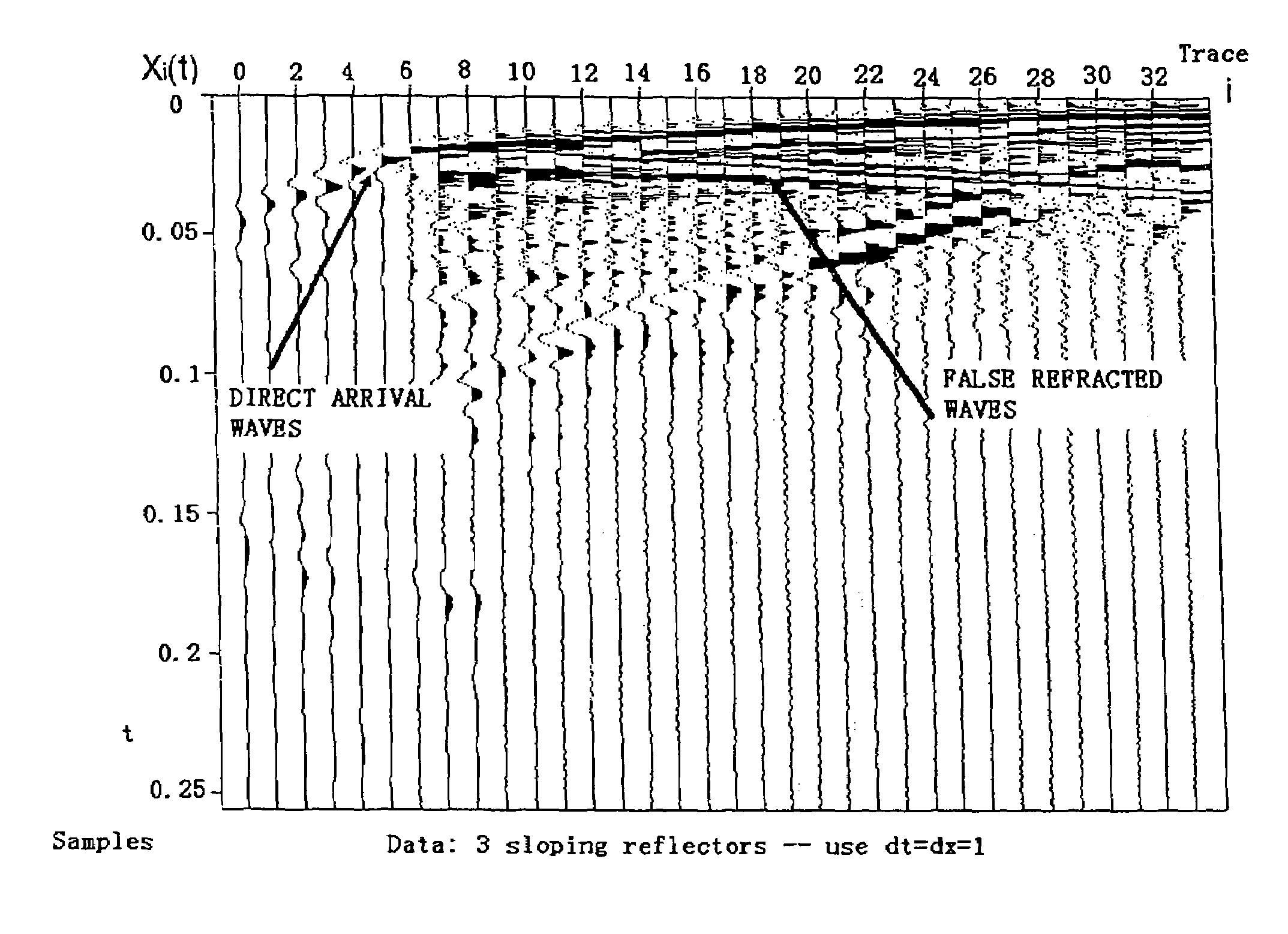
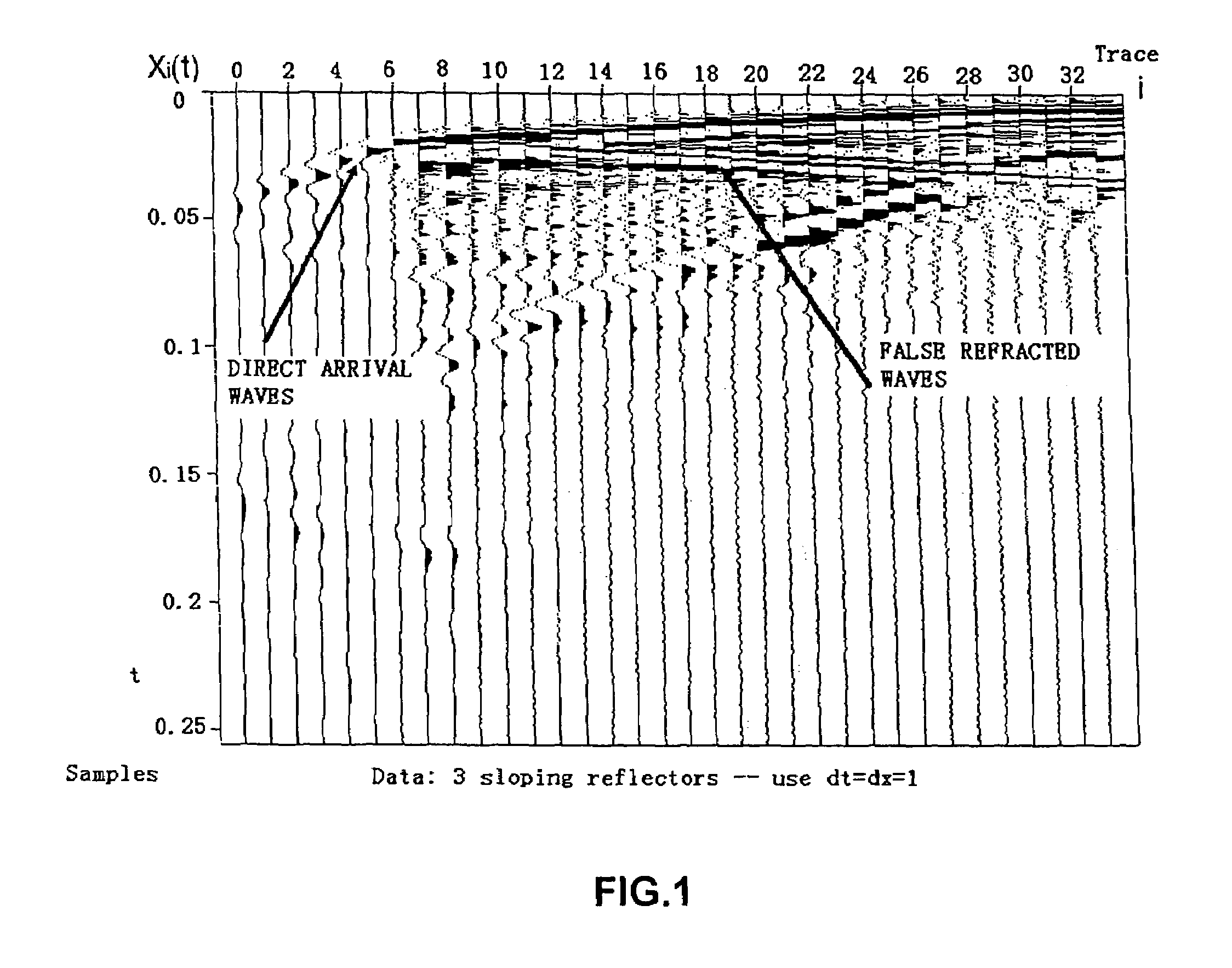
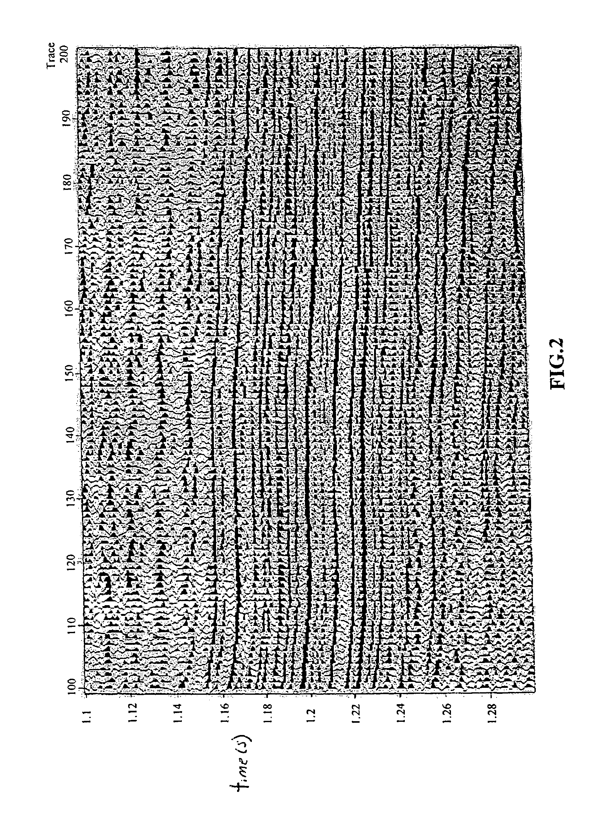
[0029]The object of the following example is to improve the seismic resolution by the said vertical seismic resolution of the seismic profiling, which is obtained by adopting the principle of the present invention, in order to show actual improvement over the regular seismic profiling. It is well-known to those of skill in the art that an event in a seismic profile is measured as being from the top of the peak (black in the figures) to the bottom of the trough (white in the figures).

[0030]According to the step (1) of the said method of the present invention, the vertical seismic record-xi(t) is obtained at the near-surface in the S area by usi...


PUM


Abstract

A method for improving the seismic resolution in the field of petroleum exploration and development, using the steps of: (1) ensuring the depth and the velocity of the low-velocity layer and the high-velocity layer and the characteristic of the frequency spectrum of the seismic wave at the near-surface using the borehole seismic survey; (2) separating the ghost wave from the seismic record in the high-velocity layer using the processing method of the vertical seismic profiling, and improving the SNR of the seismic record of the direct wave at the high-velocity layer using the uphole stacking of the vertical seismic profiling; (3) evaluating the de-convolution operator of the near-surface by the convolution math-physics equation; (4) evaluating the seismic record with high resolution by the de-convolution math-physics equation; (5) providing the band-pass filtering and geologic interpretation to the seismic record with high resolution. Using this method, the apparent dominant frequency may reach 200 Hz and higher, the vertical seismic resolution is improved, and the problem of recognizing the thin layer by the present seismic exploration is resolved.

Description

FIELD OF THE INVENTION[0001]The invention relates to a method in the field of petroleum exploration and development, especially to a method for improving the seismic resolution in the field of seismic exploration.TECHNICAL BACKGROUND OF THE INVENTION[0002]The seismic record is the recorded result of the seismic wavelet, which is produced by the hypocenter, recorded after the seismic wavelet spreads to the underground and is reflected back to the ground when met by the reflecting boundary. The vertical seismic resolution depends on the dominant frequency of the seismic wavelet, which is affected by the excited condition and spread condition. When the hypocenter of the seismic dynamite is generated, the wave dispersion of the seismic wavelet is improved by the amount of the dynamite or loosed by the stratum at the point of the detonation, therefore the dominant frequency of the seismic wavelet will be lowered. The attenuation, such as absorption, scattering, etc. takes place during th...

Claims


Application Information

Patent Timeline
Patent Type & Authority Patents(United States)
IPC IPC(8): G01V1/28G01V1/36G01V1/00G01V1/30G01V1/50
CPCG01V1/003G01V1/28G01V2210/20
Inventor LI, ZISHUNXU, YOUMEI
Owner PETROCHINA CO LTD
Why Eureka
Try Eureka