Microphone with internal damping

a technology of damping and microphones, applied in the field of miniature microphones, can solve the problems of affecting the frequency response of the microphone,

Inactive Publication Date: 2008-08-19
SONION NEDERLAND
View PDF154 Cites 81 Cited by
  • Summary
  • Abstract
  • Description
  • Claims
  • Application Information

AI Technical Summary

Problems solved by technology

A damping screen, however, can become clogged as debris and foreign material accumulate on its surface.
As the dampening screen becomes increasingly clogged, the microphone's frequency response may depart from the specification.
A shaped structure can also become less effective as debris accumulates, since the shaped structure depends on its shape to create the desired dampening effect.
In both of the above cases, the accumulation of debris, such as dust, hairspray, pollen, and other particles, may adversely affect the frequency response of the microphone and may even cause it to malfunction.
The escaping air results in a damping of the frequency response of the microphone.

Method used


Image

  • Microphone with internal damping
  • Microphone with internal damping
  • Microphone with internal damping

Examples


Embodiment Construction

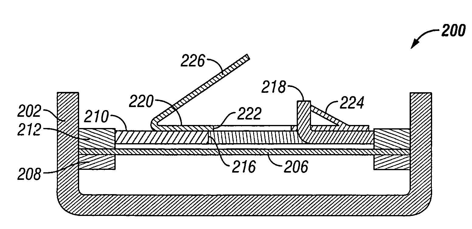
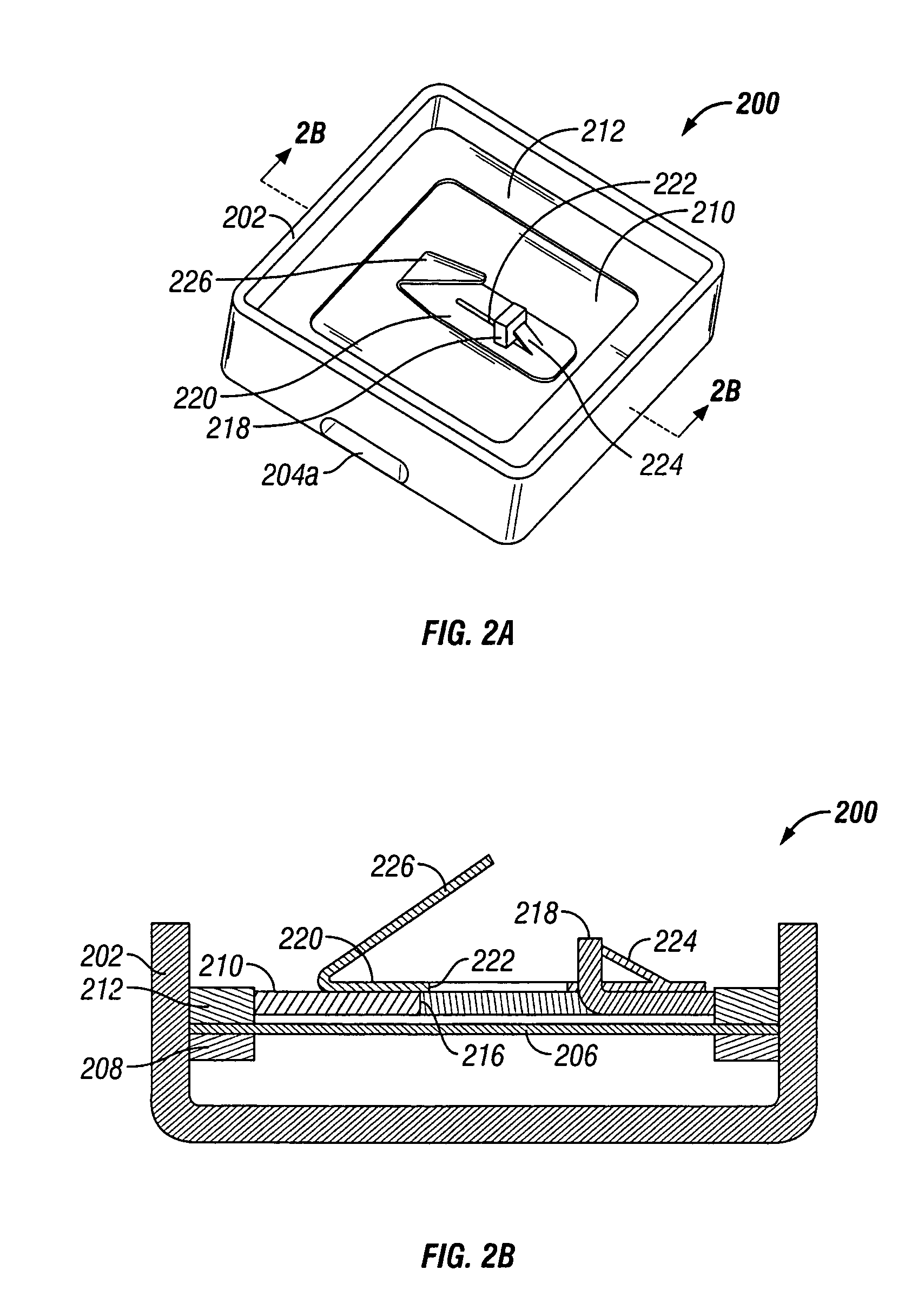
[0020]As mentioned above, embodiments of the invention provide a method and apparatus for damping the frequency response in a microphone of a listening device, such as a hearing aid. The method and apparatus of the invention makes use of a hole in the backplate by partially covering the hole to control the frequency response. A substantially airtight seal is formed between the backplate and a frame supporting the backplate to prevent air from escaping through the seal.

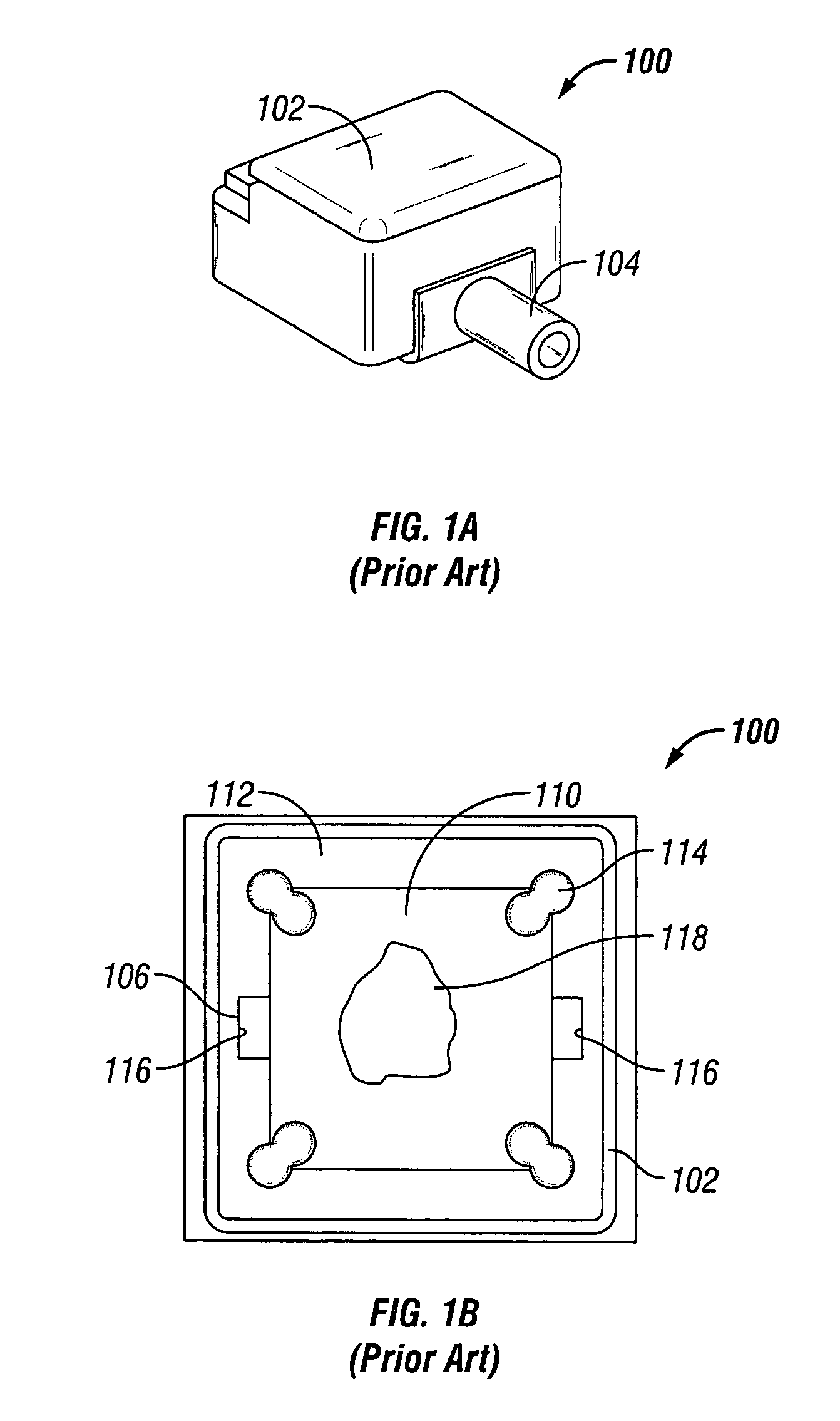
[0021]A prior art microphone 100 for a conventional listening device is shown in FIGS. 1A-1B. Referring first to the perspective view of FIG. 1A, the microphone 100 includes a housing 102 that houses the audio components inside the microphone 100. The housing 102 may be of a size and shape that allows the microphone 100 to be used in miniature listening devices, such as hearing aids. A sound inlet 104 in the housing 102 enables sound waves to enter the microphone 100.

[0022]FIG. 1B is a top cut away view of the micropho...


PUM


Abstract

Method and apparatus are disclosed for damping the resonance frequency in a microphone. The method and apparatus of the invention involve providing an elastomeric frame to support the backplate. The elastomeric frame forms a substantially air tight seal around the backplate. A hole is formed in the backplate and a cover having an opening therein is placed over the hole in the backplate. The frequency response of the microphone may then be controlled by precisely controlling the size, shape, and / or location of the opening in the cover overlaying the hole. The cover may also serve as an electrical contact to other components in the microphone.

Description

FIELD OF THE INVENTION[0001]The present invention relates to miniature microphones used in listening devices, such as hearing aids. In particular, the present invention relates to a method and apparatus for damping the frequency response in such miniature microphones.BACKGROUND OF THE INVENTION[0002]A conventional listening device such as a hearing aid includes, among other things, a microphone and a receiver. The microphone receives sound waves and converts the sound waves to an audio signal. The audio signal is then processed (e.g., amplified) and provided to the receiver. The receiver converts the processed audio signal into an acoustic signal and subsequently broadcasts the acoustic signal to the user.[0003]The microphone generally has a rigid, electrically charged backplate and a moveable metallic diaphragm. The diaphragm divides the inner volume of the microphone into a front volume and a rear volume. Sound waves enter the microphone via a sound inlet and pass into the front v...

Claims


Application Information

Patent Timeline
Patent Type & Authority Patents(United States)
IPC IPC(8): H04R25/00
CPCH04R19/04H04R19/016H04R25/00
Inventor MOGELIN, RAYMONDDUBBELDEMAN, EDDYAPPEL, RONALD
Owner SONION NEDERLAND
Why Eureka
Try Eureka