Gathering and picking device

Inactive Publication Date: 2008-08-26
MASCHFAB KEMPER
View PDF9 Cites 3 Cited by
  • Summary
  • Abstract
  • Description
  • Claims
  • Application Information

AI Technical Summary

Benefits of technology

[0005]It is an object of the present invention to provide an improved gathering and picking device

Problems solved by technology

One disadvantage of this device can be seen in the relatively long structural length caused by the use of the cutting mechanisms and the picking units arranged downstream from th

Method used


Image

  • Gathering and picking device
  • Gathering and picking device
  • Gathering and picking device

Examples


Embodiment Construction

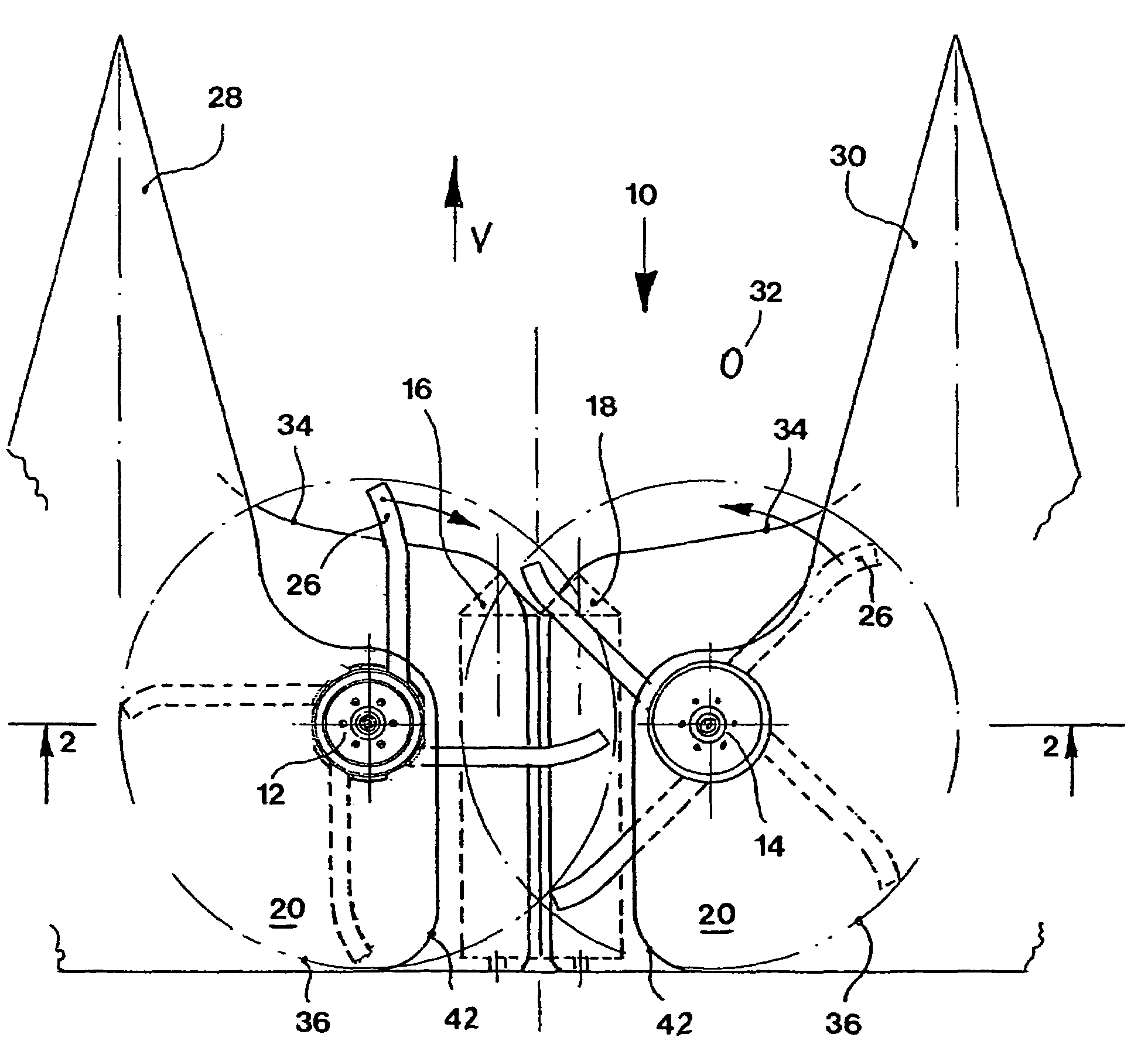
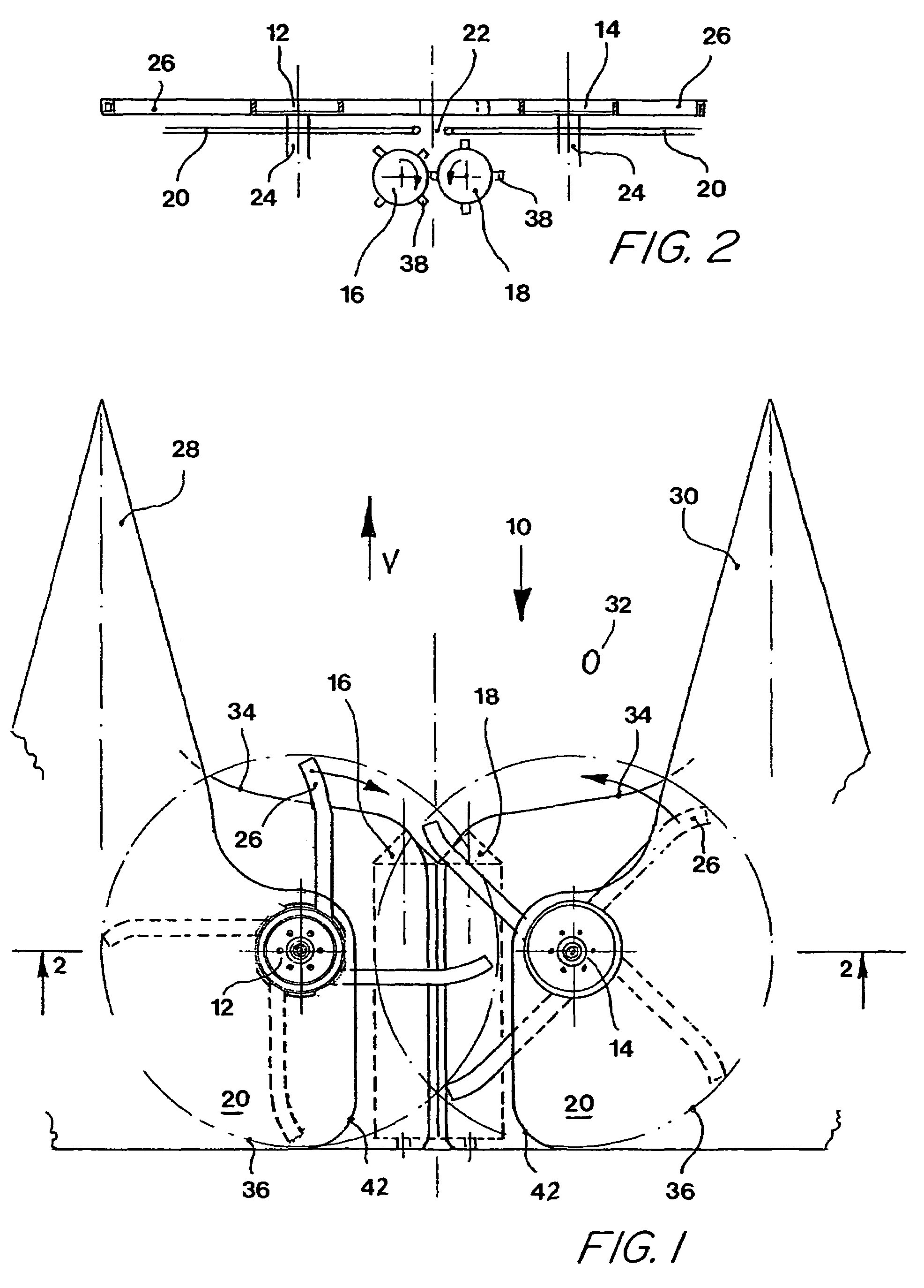
[0013]FIG. 1 shows a gathering and picking device 10 of a harvester. The complete harvester usually comprises a series of gathering and picking devices 10. However, it would also be conceivable to provide the harvester with only one individual gathering and picking device 10.

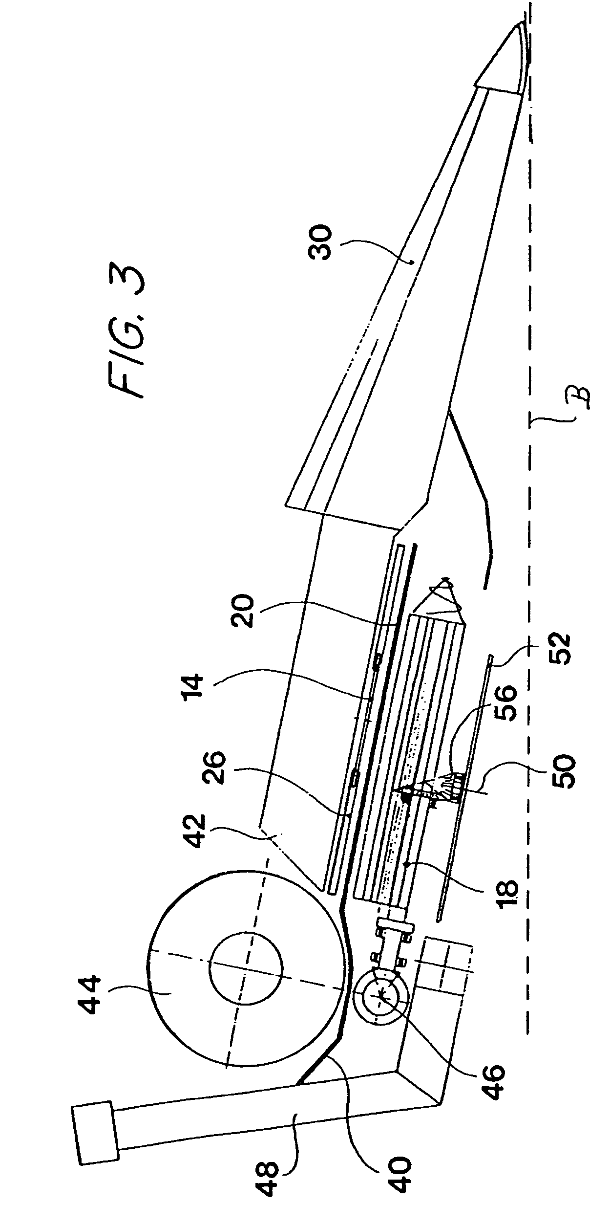
[0014]The gathering and picking device 10 contains a first gathering element 12 and a second gathering element 14 for grasping and drawing in the plants to be harvested, as well as a first picking roll 16 and a second picking roll 18 that are arranged underneath a picking gap 22 in a stripping plate 20.

[0015]With respect to the forward driving direction V, the first gathering element 12 is situated on the left side of the picking gap 22 and the second gathering element 14 is arranged on the right side of the picking gap 22. The first gathering element 12 and the second gathering element 14 are arranged such that they are rotatable about approximately vertical and parallel axes, and can be set in rotation by thei...


PUM


Abstract

A gathering and picking device comprising a first gathering element that is arranged on a first side of a picking gap and a second gathering element that is arranged on a second side of a picking gap opposite the first gathering element. Both gathering elements are rotated about a predominantly vertical axes and are provided with carrier elements that grasp standing plants. The carrier elements introduce the standing plants into the picking gap and convey the standing plants over at least part of the length of the picking gap.

Description

FIELD OF THE INVENTION[0001]The present invention is directed to a gathering and picking device with a first gathering element arranged on a first side of a picking gap and a second gathering element arranged on the second side of the picking gap opposite the first gathering element.BACKGROUND OF THE INVENTION[0002]U.S. Pat. No. 5,916,113 A describes a corn harvesting attachment that can be attached to a self-propelled harvesting machine, wherein a series of conveying elements with approximately vertical axes of rotation are arranged along both sides of the picking gap. The conveying elements are provided with conveying fingers that are oriented radially with respect to the axis of rotation and convey the plants along the picking gap. With respect to the conveying direction, the conveying elements are arranged, offset relative to one another, on both sides of the picking gap such that the plants are conveyed due to their alternating interaction with the conveying elements on both si...

Claims


Application Information

Patent Timeline
IPC IPC(8): A01D45/02
CPCA01D45/025Y02A40/28
Inventor KAPPELHOFF, HANS
Owner MASCHFAB KEMPER
Why Eureka
Try Eureka