
Vehicle lighting device

a vehicle lighting and vehicle technology, applied in the direction of lighting support devices, lighting and heating apparatus, instruments, etc., can solve the problem that the light emitted by the vehicle lighting device cannot be accurately controlled

Inactive Publication Date: 2008-08-26
KOITO MFG CO LTD
View PDF9 Cites 18 Cited by
  • Summary
  • Abstract
  • Description
  • Claims
  • Application Information

AI Technical Summary

Problems solved by technology

While the utilization factor of bundles of rays of light from the light emitting element can be enhanced by adopting the vehicle lighting device described in the aforesaid JP-A-2001-283616, in the vehicle lighting device so described, there is a problem that light emitted from this vehicle lighting device cannot be accurately controlled since not only the light from the light emitting element that is reflected on the primary reflector, but also direct light from the light emitting element, are designed to be incident on the secondary reflector.

Method used


Image

  • Vehicle lighting device
  • Vehicle lighting device
  • Vehicle lighting device

Examples


Embodiment Construction

[0035]Although the invention will be described below with reference to an exemplary embodiment and modifications thereof, the following exemplary embodiment and modifications do not restrict the invention. The exemplary embodiment of the invention will be described using the accompanying drawings.

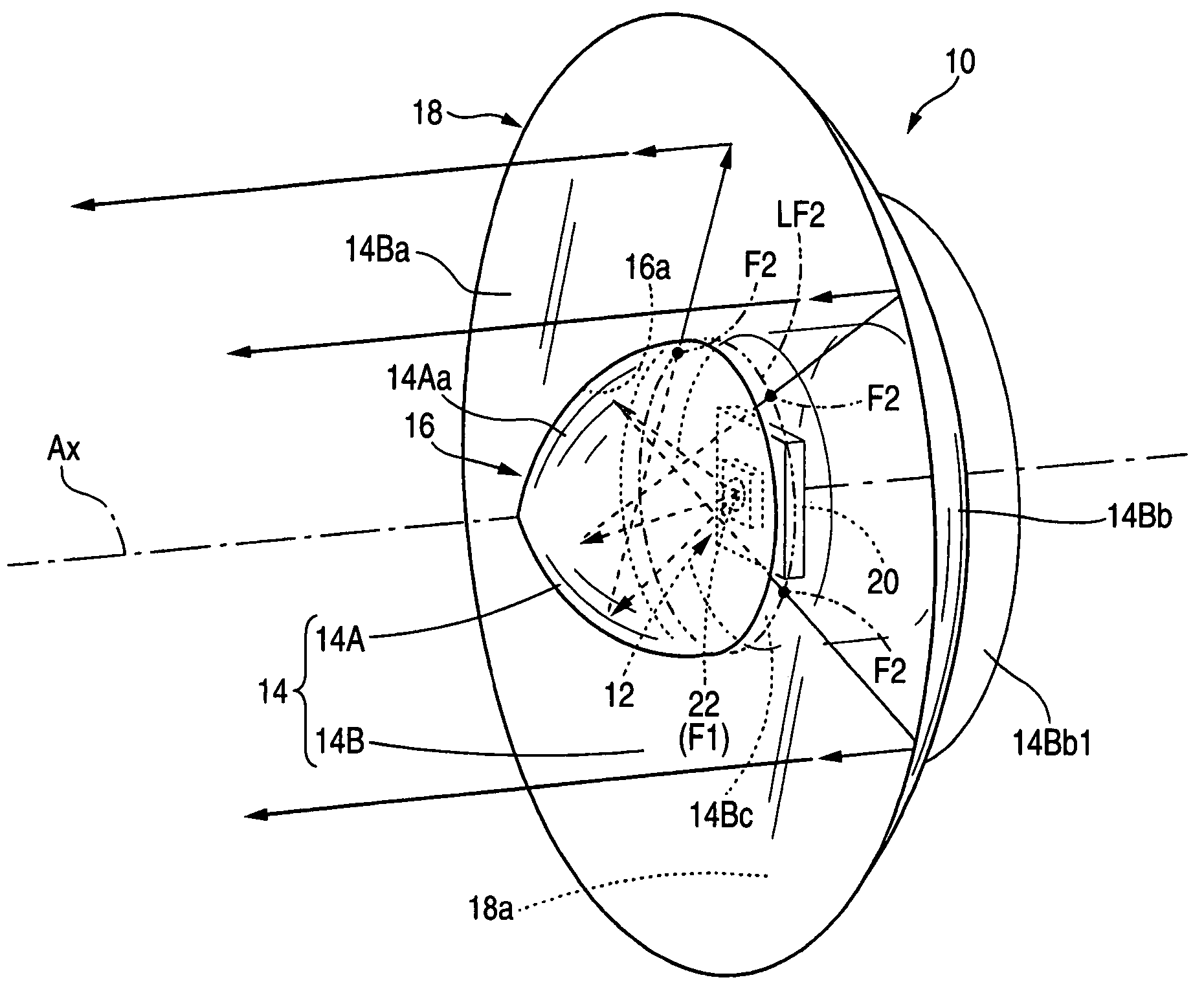
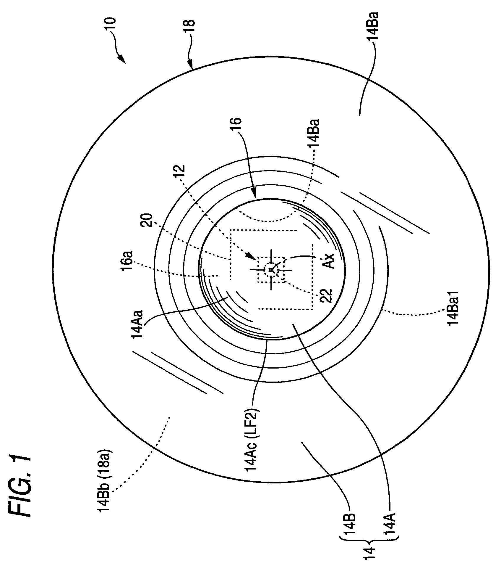
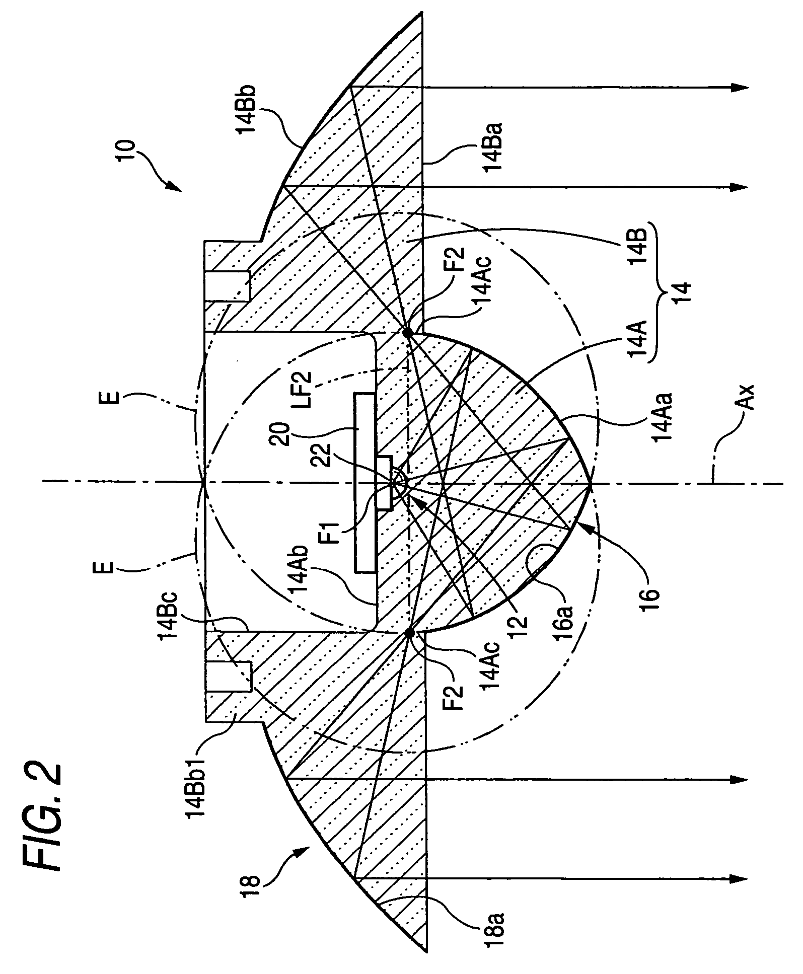
[0036]FIGS. 1 and 2 are, respectively, a front view and a top sectional view which show a vehicle lighting device 10 according to the embodiment of the invention, and FIG. 3 is a drawing which shows in detail a main part in FIG. 2. In addition, FIG. 4 is a perspective view which shows the vehicle lighting device.

[0037]As shown in these figures, the vehicle lighting device 10 is a lamp unit that is incorporated as part of a headlamp and includes a light emitting element 12 disposed to direct light toward the front of the lighting device 10. A light emitting center of the light emitting element is positioned on an optical axis Ax that extends in a longitudinal direction of the lighting device...


PUM


Abstract

A vehicle light emitting device including a light emitting element, a primary reflector, and a secondary reflector. A reflecting surface of the primary reflector has a shape of a substantially dome-shaped body of revolution formed by rotating about the optical axis Ax an ellipse E which has a primary focal point F1 which is a point near the light emitting element and a secondary focal point F2 which is a point near the reflecting surface. The primary reflector includes a belt-shaped region, which straddles a ring-shaped locus of the secondary focal point F2 and is configured as a light translucent portion, whereby reflected light from the primary reflector is caused to temporarily converge on the secondary focal point F2 in each cross-section of the body of revolution including the optical axis Ax and is thereafter caused to be incident on the secondary reflector as a diffused light.

Description

[0001]This application claims foreign priority from Japanese Patent Application No. 2004-338663, filed Nov. 24, 2004, the entire disclosure of which is herein incorporated by reference.BACKGROUND OF THE INVENTION[0002]1. Field of the Invention[0003]The present invention relates to a vehicle lighting device including a light emitting element, such as a light emitting diode, as a light source.[0004]2. Description of Related Art[0005]In recent years, lighting devices, which use as light sources light emitting elements, such as light emitting diodes, have been developed for use in vehicle lighting devices such as headlamps.[0006]In relation to the development of these lighting devices, Japanese Patent Publication No. 2001-283616 describes a vehicle lighting device including a primary reflector which reflects light from a light emitting element disposed on an optical axis extending in a longitudinal direction of the lighting device in such a manner as to be directed towards the front of ...

Claims


Application Information

Patent Timeline
Patent Type & Authority Patents(United States)
IPC IPC(8): F21V7/00F21Y101/00
CPCF21K9/00F21S48/1159F21S48/1329F21S48/1388G02B19/0061G02B17/086G02B19/0028F21V7/0091F21Y2101/02F21Y2115/10F21S41/143F21S41/155F21S41/24F21S41/255F21S41/285F21S41/321F21S41/322F21S41/365
Inventor TANAKA, HIDETADAKOMATSU, MOTOHIRO
Owner KOITO MFG CO LTD
Learn More