Determination of effective resistance between a power sourcing equipment and a powered device

a technology of power sourcing equipment and effective resistance, which is applied in the direction of data switching current supply, data switching details, instruments, etc., can solve the problems of over-standard limitations on powered devices, waste of power, and inability to determine the effective resistance between pse and pd, so as to achieve accurate determination and better power allocation

Active Publication Date: 2008-08-26
CISCO TECH INC
View PDF14 Cites 57 Cited by
  • Summary
  • Abstract
  • Description
  • Claims
  • Application Information

AI Technical Summary

Benefits of technology

[0011]Advantageously, determining the effective resistance of the cable and connections between the PSE and the PD allows for better allocation of power, since the actual power to be allocated to the PSE in order to support the PD classification power is more accurately determined.

Problems solved by technology

The above standard is limited to a powered device (PD) having a maximum power requirement during operation of 12.95 watts.
In the absence of a determination of the effective resistance, a worst case effective resistance is utilized, thereby leading to wasted power.
Unfortunately, no means of determining the effective resistance between the PSE and the PD is provided.

Method used


Image

  • Determination of effective resistance between a power sourcing equipment and a powered device
  • Determination of effective resistance between a power sourcing equipment and a powered device
  • Determination of effective resistance between a power sourcing equipment and a powered device

Examples


Embodiment Construction

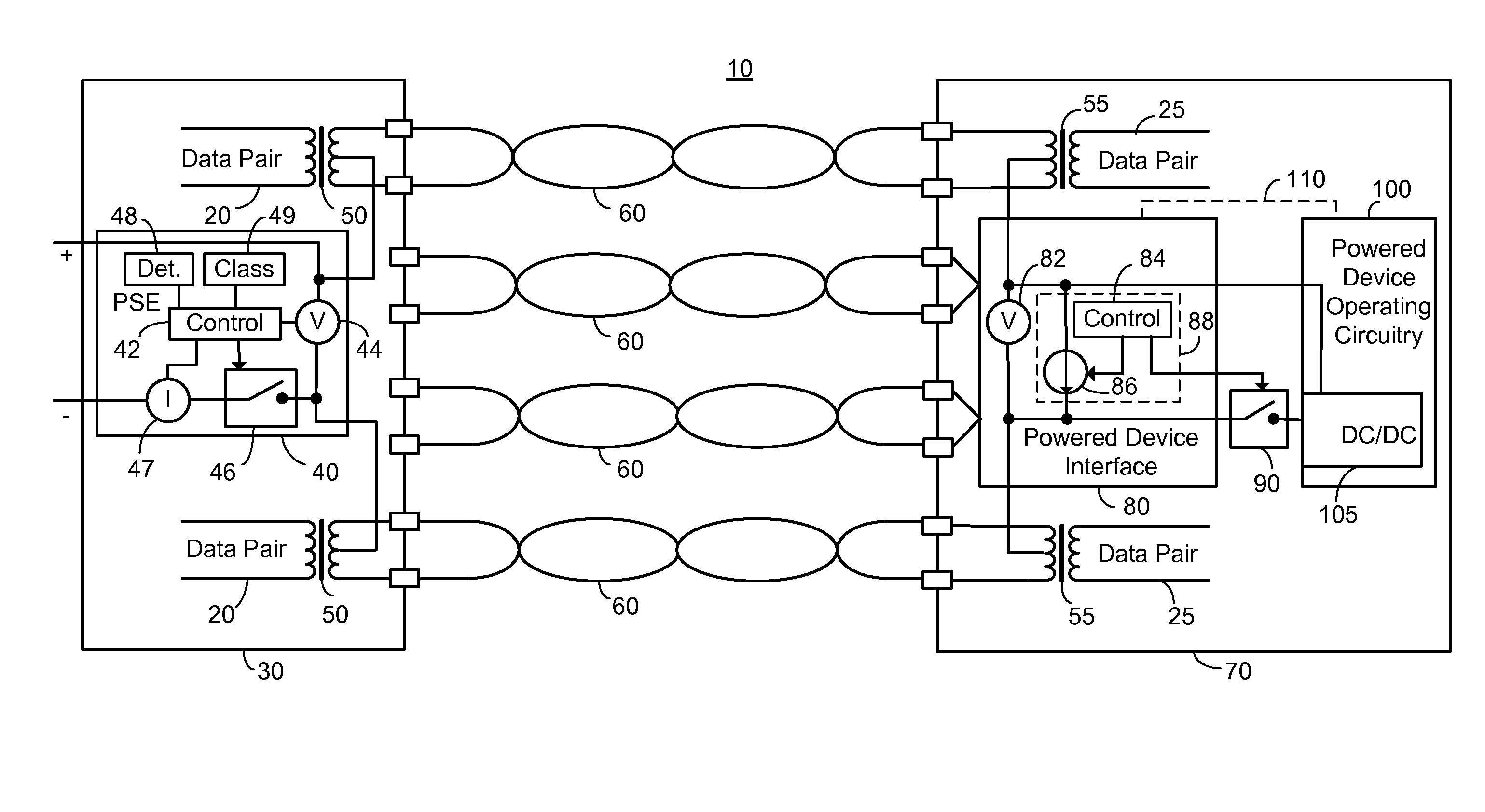
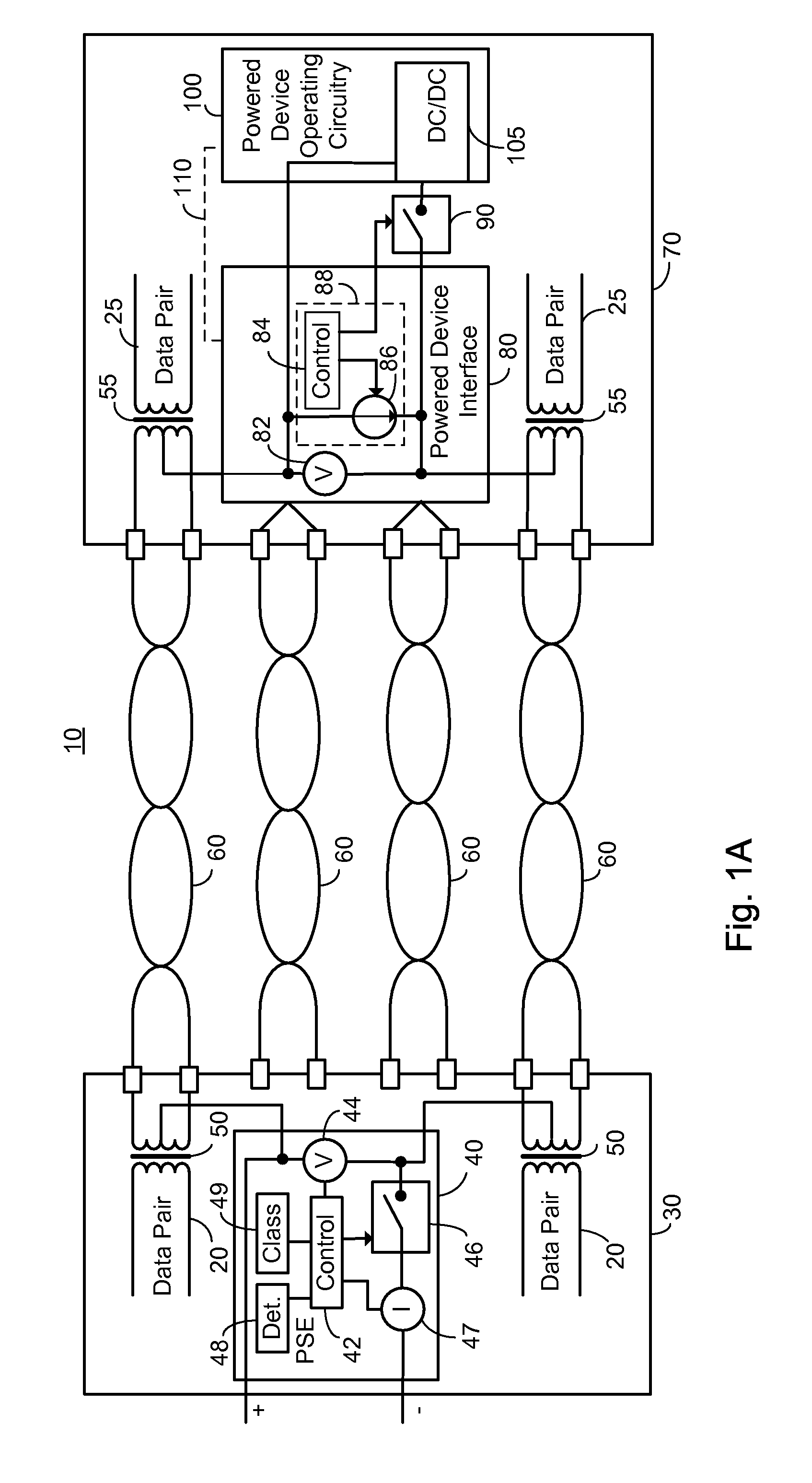
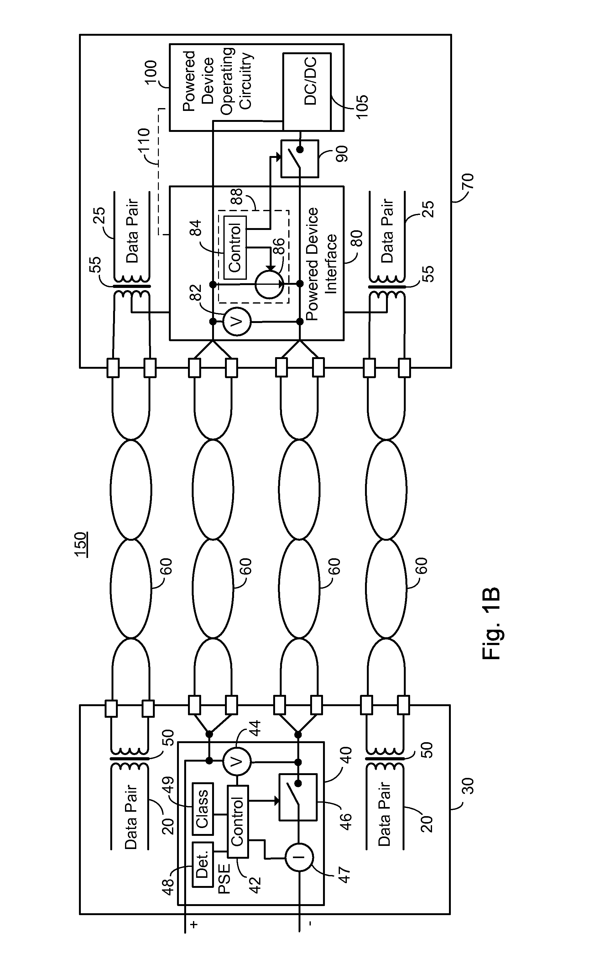
[0043]The present embodiments enable a method for determining the effective resistance between the PSE and the PD, the method comprising: impressing a plurality of disparate current flow levels between the PSE and the PD prior to connecting power to PD operational circuitry; measuring the voltage at the PD interface at each of the plurality of impressed current flow levels; measuring the voltage at the PSE at each of the plurality of impressed current flow levels; and determining the effective resistance responsive to the plurality of voltage measurements at the PD, the plurality of voltage measurements at the PSE and the current flow levels.

[0044]Preferably the current flow levels are measured, and the measured current flow levels are utilized in determining the effective resistance. Preferably, the plurality of current flow levels are associated with PD-PSE communication.

[0045]Advantageously, determining the effective resistance of the cable and connections between the PSE and the...


PUM


Abstract

A method of determining an effective resistance between a power sourcing equipment and a powered device, the powered device exhibiting an interface and an operational circuitry, the method comprising: prior to connecting power to the operational circuitry of the powered device, impressing two disparate current flow levels (I1, I2) between the power sourcing equipment and the powered device; measuring the voltage at the powered device interface (VPD1, VPD2) responsive to each of the impressed disparate current levels; measuring the voltage at the power sourcing equipment (VPSE1, VPSE2) responsive to each of the impressed disparate current levels; and determining the effective resistance between the power sourcing equipment and the powered device responsive to the VPD1, VPD2, VPSE1, VPSE2, I1 and 12.

Description

BACKGROUND OF THE INVENTION[0001]The invention relates generally to the field of power over local area networks, particularly Ethernet based networks, and more particularly to a method of determining the effective resistance between a power sourcing equipment and a powered device.[0002]The growth of local and wide area networks based on Ethernet technology has been an important driver for cabling offices and homes with structured cabling systems having multiple twisted wire pairs. The structured cable is also known herein as communication cabling and typically comprises four twisted wire pairs. In certain networks only two twisted wire pairs are used for communication, with the other set of two twisted wire pairs being known as spare pairs. In other networks all four twisted wire pairs are used for communication. The ubiquitous local area network, and the equipment which operates thereon, has led to a situation where there is often a need to attach a network operated device for whic...

Claims


Application Information

Patent Timeline
Patent Type & Authority Patents(United States)
IPC IPC(8): G01R27/08
CPCH04L12/10G01R27/16G06F1/26
Inventor ADMON, DANELKAYAM, SHIMON
Owner CISCO TECH INC
Why Eureka
Try Eureka