Prosthetic foot with a resilient ankle

a technology of prosthetic feet and resilient ankles, applied in the field of prosthetic feet, can solve the problems that the development of functional and natural artificial feet has been limited only by material and imagination, and achieve the effect of softer heel and improved shock absorption

Inactive Publication Date: 2008-09-02
FREEDOM INNOVATIONS INC
View PDF113 Cites 36 Cited by
  • Summary
  • Abstract
  • Description
  • Claims
  • Application Information

AI Technical Summary

Benefits of technology

[0009]The continued development of improved prosthetic feet is an ongoing goal. It has been recognized that it would be advantageous to develop a prosthetic foot with improved shock absorption or a softer heel.
[0014]In accordance with another more detailed aspect of the present invention, the ankle section of the forefoot portion can include a discrete, straight section oriented substantially vertically. A first curved section can interconnect the attachment section and the straight section, and a second curved section can interconnect the straight section and the arch section. The discrete, straight ankle section with curved sections on both sides allow extra length to store and return energy during use, contribute to extra spring or cushion of the foot, and improve vertical shock resistance.

Problems solved by technology

With respect to prosthetic feet, the development of a functional and natural artificial foot has been limited only by material and imagination.

Method used


Image

  • Prosthetic foot with a resilient ankle
  • Prosthetic foot with a resilient ankle
  • Prosthetic foot with a resilient ankle

Examples


Embodiment Construction

[0023]Reference will now be made to the exemplary embodiments illustrated in the drawings, and specific language will be used herein to describe the same. It will nevertheless be understood that no limitation of the scope of the invention is thereby intended. Alterations and further modifications of the inventive features illustrated herein, and additional applications of the principles of the inventions as illustrated herein, which would occur to one skilled in the relevant art and having possession of this disclosure, are to be considered within the scope of the invention.

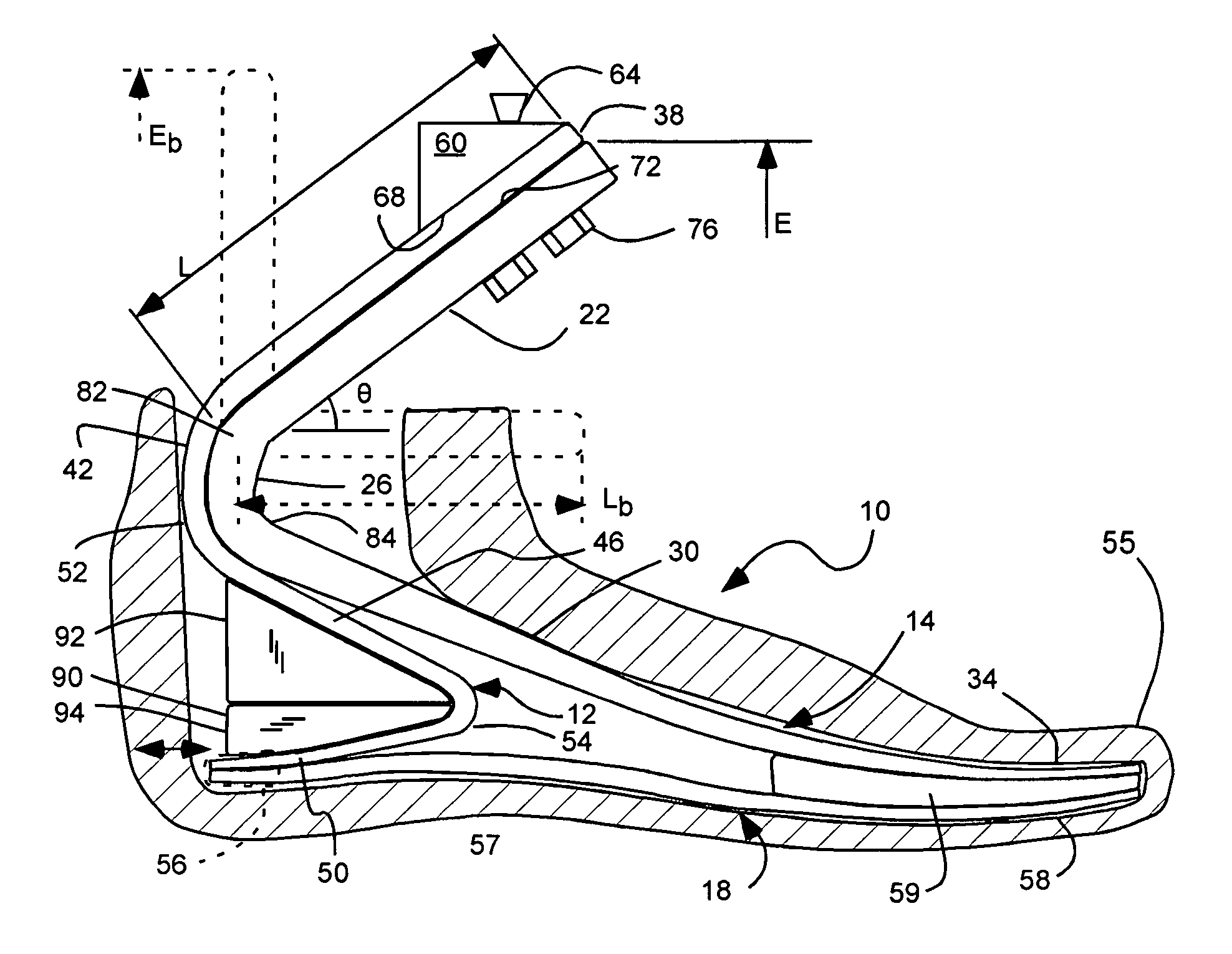
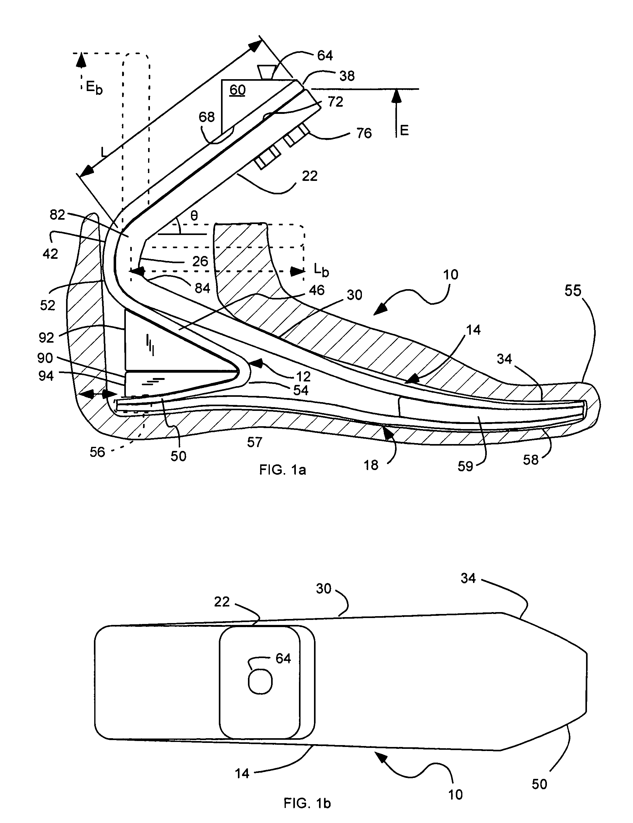
[0024]As illustrated in FIGS. 1a and b, a prosthetic foot, indicated generally at 10, in accordance with the present invention is shown with an elongated rear ankle portion 12 for absorbing shock and cushioning a limb or stump of an amputee. The prosthetic foot 10 can include an elongated, upper forefoot portion or forefoot 14, and a lower footplate 18 disposed under the forefoot portion 14 and the ankle portion ...


PUM


Abstract

A prosthetic foot device includes an elongated upper forefoot portion, an ankle portion, and a lower footplate. The forefoot portion can extend rearwardly through an upper attachment section, downwardly through an ankle section, forwardly through an arch section, and to a toe section. The ankle portion can attach to the forefoot portion, and can extend rearwardly through an upper attachment section, downwardly through an ankle section, forwardly under the ankle section of the forefoot portion, and rearwardly to a heel section, in a substantial s-shaped profile. The lower footplate is disposed under the ankle and forefoot portions, and can extend through a heel section, an arch section, and to a toe section. The upper forefoot portion, the ankle portion, and the lower footplate are flexible to store energy and resilient to return energy.

Description

[0001]This application is a continuation in part of U.S. patent application Ser. No. 10 / 268,014, filed on Oct. 8, 2002, now U.S. Pat. No. 6,929,665 B2, which is incorporated herein by reference.BACKGROUND OF THE INVENTION[0002]1. Field of the Invention[0003]The present invention relates generally to prosthetic feet. More particularly, the present invention relates to a prosthetic foot with a resilient ankle.[0004]2. Related Art[0005]Many individuals have lost a limb for various reasons including war, accident, or disease. In most instances these individuals are not only able to live relatively normal lives, but physically active lives as well. Often times, these individuals are aided in their everyday lives by a prosthetic limb. The objective of prosthesis is to provide an artificial limb that simulates the function and natural feel of the replaced limb.[0006]With respect to prosthetic feet, the development of a functional and natural artificial foot has been limited only by materia...

Claims


Application Information

Patent Timeline
Patent Type & Authority Patents(United States)
IPC IPC(8): A61F2/66A61F2/00A61F2/50A61F2/76
CPCA61F2/66A61F2/6607A61F2/76A61F2002/30434A61F2002/5003A61F2220/0041A61F2002/6642A61F2002/6664A61F2002/6671A61F2002/6678A61F2002/6685A61F2002/6621A61F2002/30433
Inventor CHRISTENSEN, ROLAND J.
Owner FREEDOM INNOVATIONS INC
Why Eureka
Try Eureka