Water resistant connector and connection connector

a technology for connecting cables and connectors, which is applied in the direction of couplings/cases, coupling device connections, and securing/insulating coupling contact members. it can solve the problems of increasing production costs, difficult to make connections, and difficult to ensure uniform adhesion of fastenings, so as to improve waterproofing and eliminate waste of cable length adjustment. , the effect of improving the efficiency of wiring operations

Active Publication Date: 2008-09-09
SMK CORP
View PDF7 Cites 8 Cited by
  • Summary
  • Abstract
  • Description
  • Claims
  • Application Information

AI Technical Summary

Benefits of technology

[0007]In light of the technical problems described above, it is an object of the present invention to provide a highly waterproof connector that can easily be attached to the terminal end of a cable. It is also an object of the present invention to provide a waterproof relay connector with these features.
[0018]Cable pinching claws may be further provided that prevent slippage of the cover and the cable on the male cover and the female cover.
[0021]Therefore, it is no longer necessary to form the connector in advance as a unit on the cable end as it was conventionally, and a cable may be cut to the necessary length on site and the waterproof connector attached.
[0022]By this means waste in cable length adjustment is eliminated, and the efficiency of wiring operations is improved.
[0023]In addition, the fastening cover comprises a male cover and a female cover, and when the male cover and female cover are attached by being fit together so as to sandwich the waterproof tube, there is a concern that the fascinating of the split part of the fastening cover may be insufficient with just the curved ribs on the inside circumference of the male cover and inside circumference of the female cover. However, if a fastening protruding piece is provided on the male cover and a fastening guide surface that is slanted towards the center side is provided on the female cover, a fastening force operates across the entire circumference of the waterproof tube because the fastening protrusion slants toward the center side so that there is pressure on the split part from the side part, and the waterproofing is improved.

Problems solved by technology

Not only does this approach increase production costs because the structure is complicated, but also it has been impossible to make connections after adjusting the length of the cable on-site, because the housing must be formed in advance as a unit on the end part of the cable.
As a result, it is difficult to control the fastening to have uniform adherence around the entire circumference of the cable.

Method used


Image

  • Water resistant connector and connection connector
  • Water resistant connector and connection connector
  • Water resistant connector and connection connector

Examples


Embodiment Construction

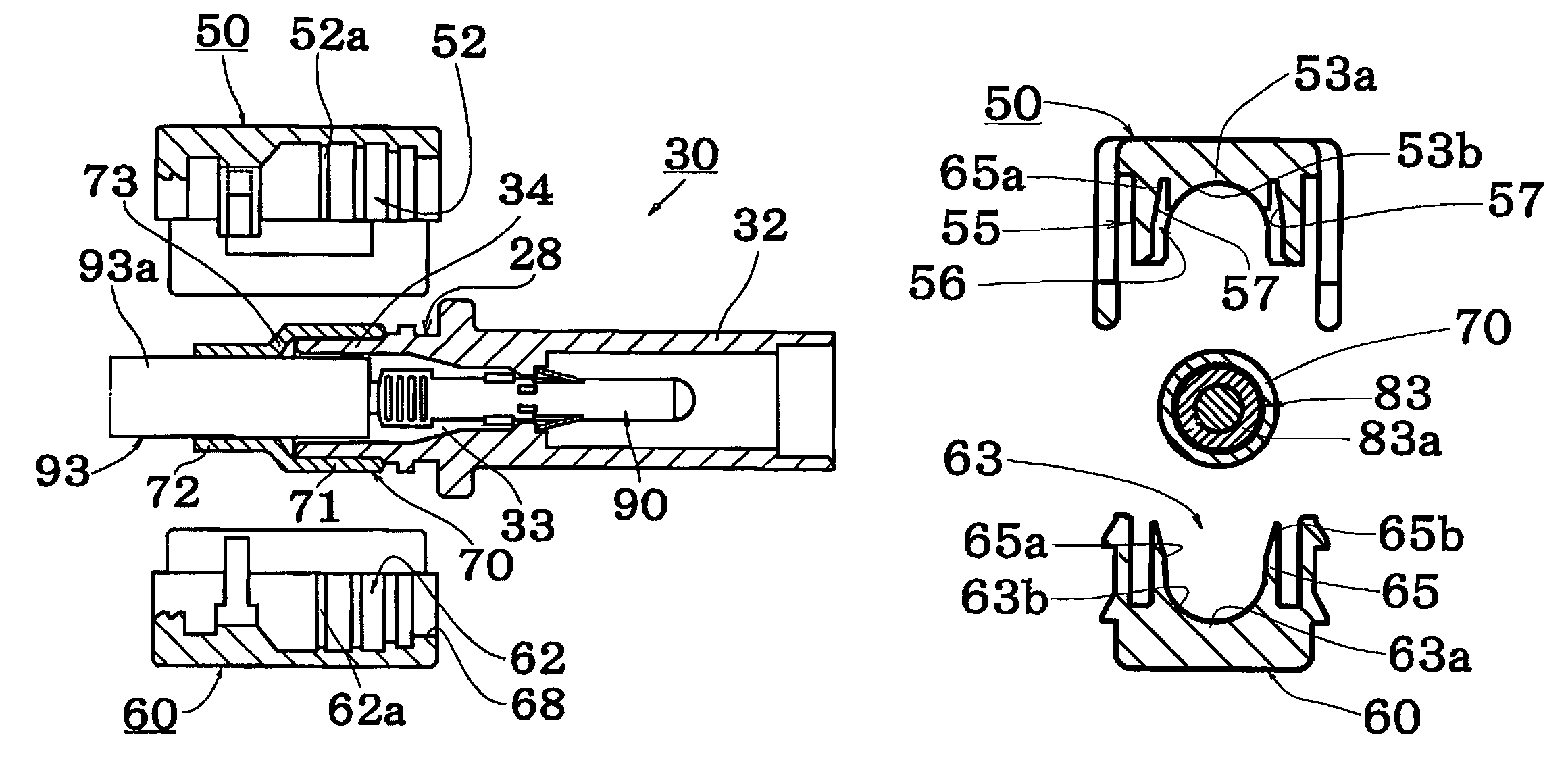
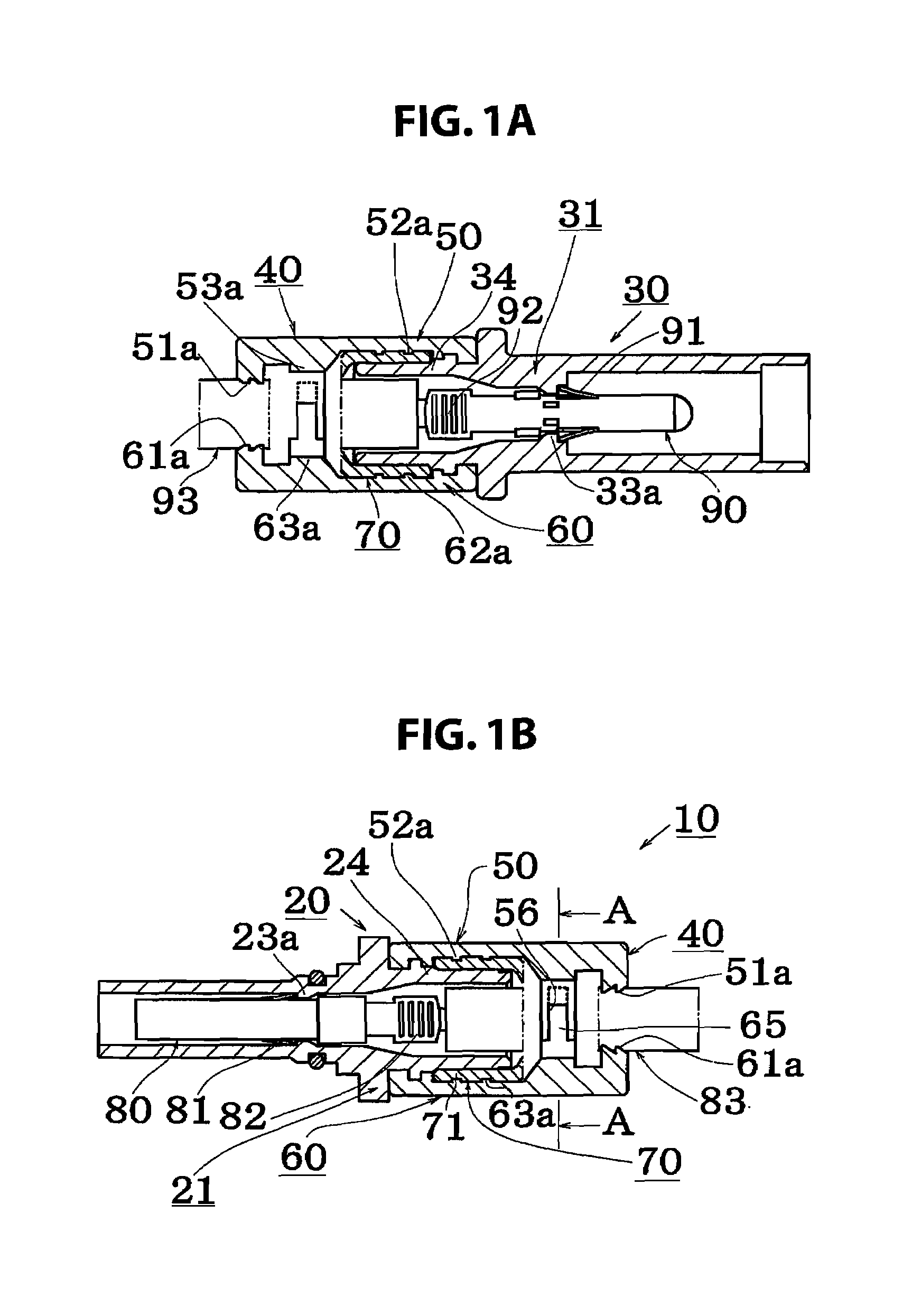
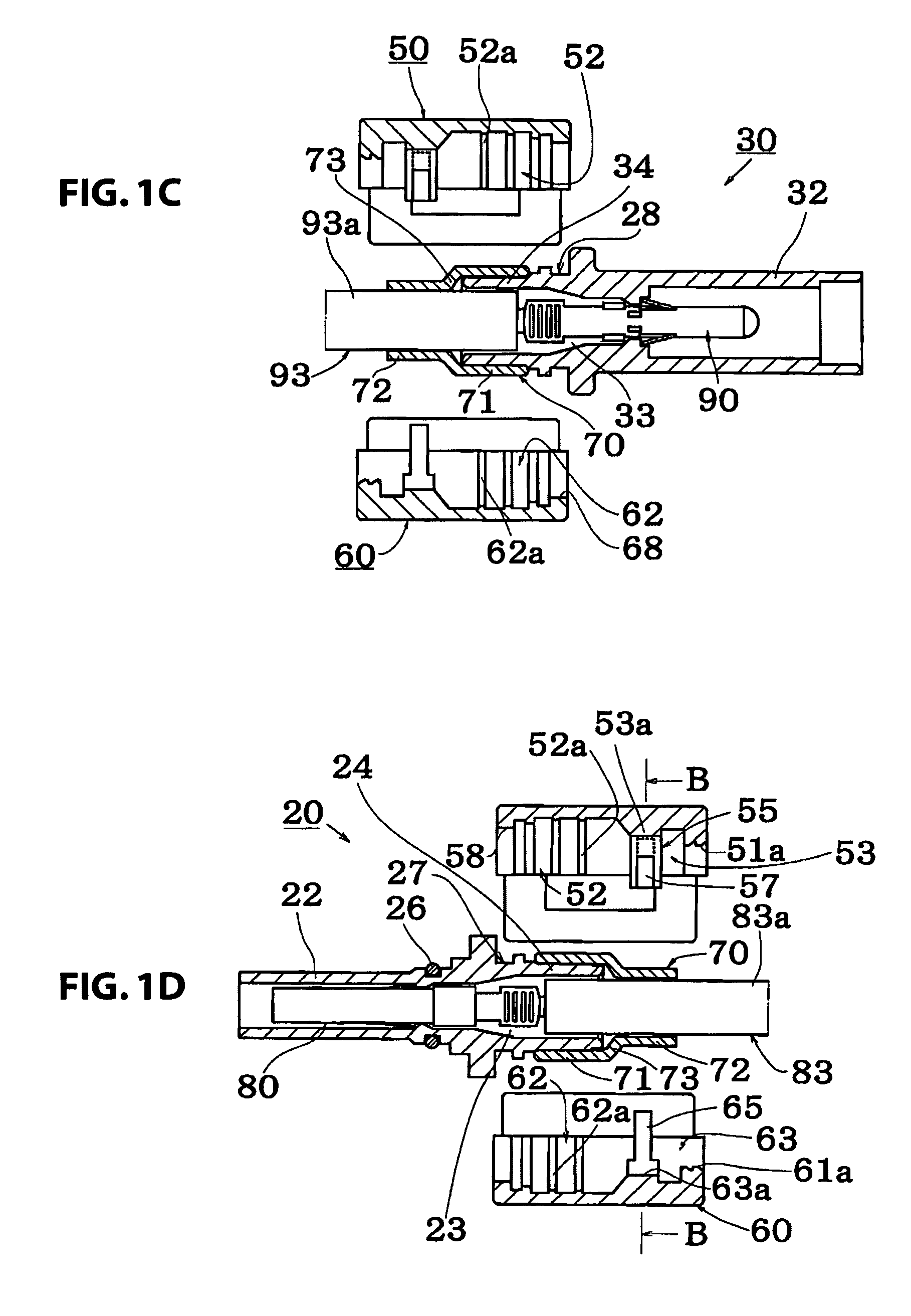
[0036]An example using the waterproof connector according to the present invention in a relay connector 10 will be described in detail with reference to the FIGS. 1(a) through 6(b).

[0037]The following table provides a key to the reference elements used in the drawings:

[0038]

10relay connector51base part20socket connector51acable pinching claw21socket housing52housing fitting recessed part22cylindrical barrier wall part52ahousing fastening rib23terminal insertion hole53cable fitting recessed part23asecuring step part53acurved rib24tube attachment part53binside surface25housing securing claw54lock arm25aclaw part54alock recessed part26seal member (O-ring)54bedge part of direction of attachment127cover positioning recessed port55fastening guide member28cover positioning recessed port56fastening guide groove30plug connector56ainsertion recessed part31plug housing57fastening guide surface32cylindrical barrier wall part58positioning protruding part33terminal insertion hole60male cover33ase...


PUM


Abstract

A waterproof connector connects to a cable, and includes a housing where a terminal connected to an end of the cable is inserted and attached, a waterproof tube attached across the periphery of the housing and a periphery of the cable and a fastening cover capable of split fastening from a peripheral side of the waterproof tube.

Description

CROSS-REFERENCE TO RELATED APPLICATION[0001]The present application claims priority under 35 U.S.C. §119 to Japanese Patent Application No. 2006-316341, filed Nov. 22, 2006, and which is hereby incorporated herein by reference in its entirety.FIELD OF THE INVENTION[0002]The present invention relates to a waterproof connector for connecting cables and a relay connector.BACKGROUND OF THE INVENTION[0003]Waterproof connectors for connecting electrical cables are known in the art. For example, FIG. 7(a) illustrates a conventional waterproof connector for interconnecting cables 183 and 193. In preparing the connector assembly, cable wire coverings 183a and 193a of cables 183 and 193 are peeled back in order for terminals 180 and 190 to be connected to the cable core wire. Next, polyethylene based elastomers 121b and 131b are formed together with rubber based elastomers 121a and 131a as a unit so as to be molded around the cable cores 183b and 193b to assure adherence to the insulative cov...

Claims


Application Information

Patent Timeline
Patent Type & Authority Patents(United States)
IPC IPC(8): H01R13/52
CPCH01R13/5202H01R13/5205H01R13/582
Inventor ARAI, ATSUSHI
Owner SMK CORP
Why Eureka
Try Eureka