Compound camera and methods for implementing auto-focus, depth-of-field and high-resolution functions

a camera and composite technology, applied in the field of composite cameras, can solve the problems of limiting the maximum resolution a camera can achieve, affecting the quality of composite images,

Inactive Publication Date: 2008-09-16
STMICROELECTRONICS SRL
View PDF9 Cites 121 Cited by
  • Summary
  • Abstract
  • Description
  • Claims
  • Application Information

AI Technical Summary

Problems solved by technology

Physical conditions limit the maximum resolution a camera can achieve.
However, the prior art conventional compound camera image processing systems mainly focus on two areas.
The problem of this approach is that the reconstructed geometry normally is not very accurate, especially on object surfaces that lack color texture.
This result in visible artifacts in the synthesized image.
A large number of cameras, in turn, produce a large amount of data to be processed.
This vastly increases the cost and complexity of the image processing system.

Method used


Image

  • Compound camera and methods for implementing auto-focus, depth-of-field and high-resolution functions
  • Compound camera and methods for implementing auto-focus, depth-of-field and high-resolution functions
  • Compound camera and methods for implementing auto-focus, depth-of-field and high-resolution functions

Examples


Embodiment Construction

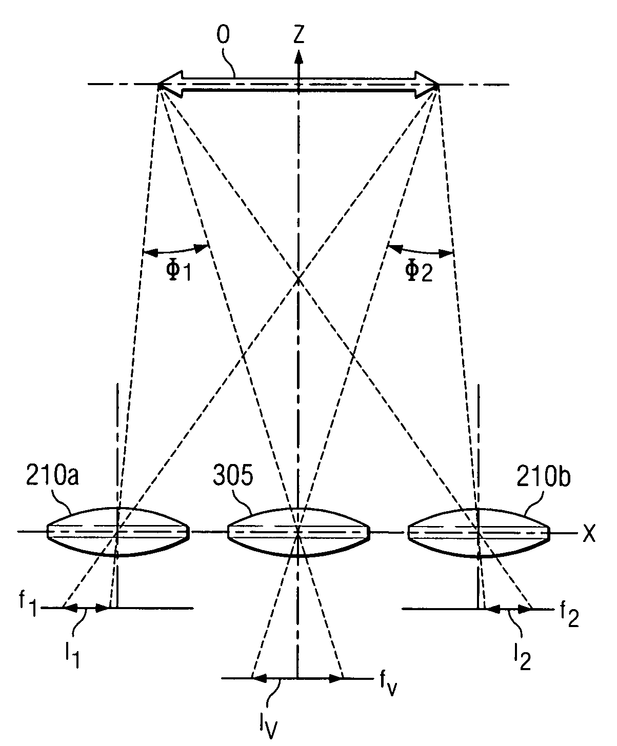
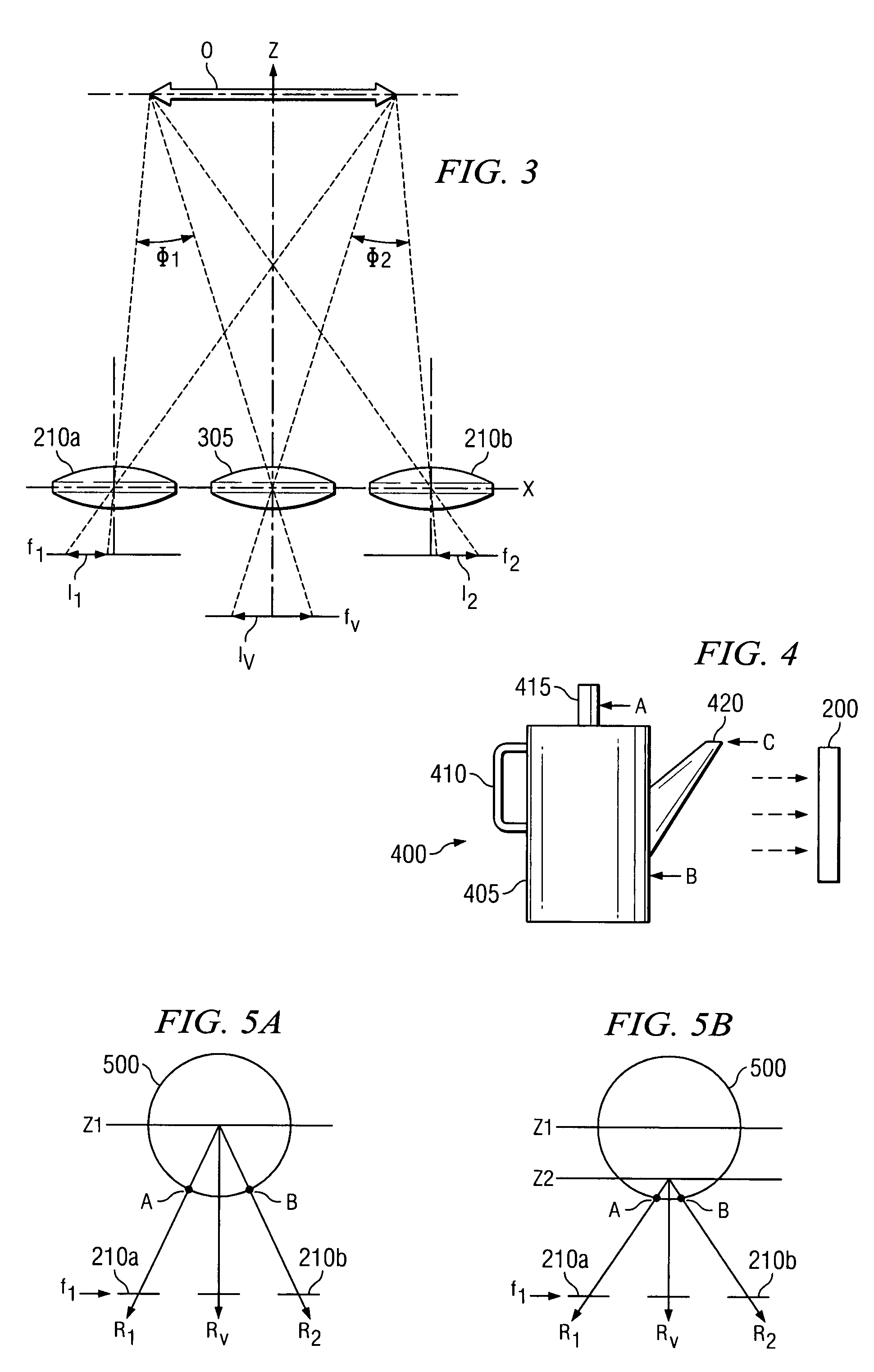
[0028]FIGS. 1 through 5, discussed below, and the various embodiments used to describe the principles of the present invention in this patent document are by way of illustration only and should not be construed in any way to limit the scope of the invention. Those skilled in the art will understand that the principles of the present invention may be implemented in any suitably arranged image processing system.

[0029]Initially, it should be noted that the items depicted in FIGS. 1-5 are not drawn to scale. Those skilled in the art will recognize that items in FIGS. 1-5 are drawn to show their relative positions in order to simplify the explanation of the operation of the present invention.

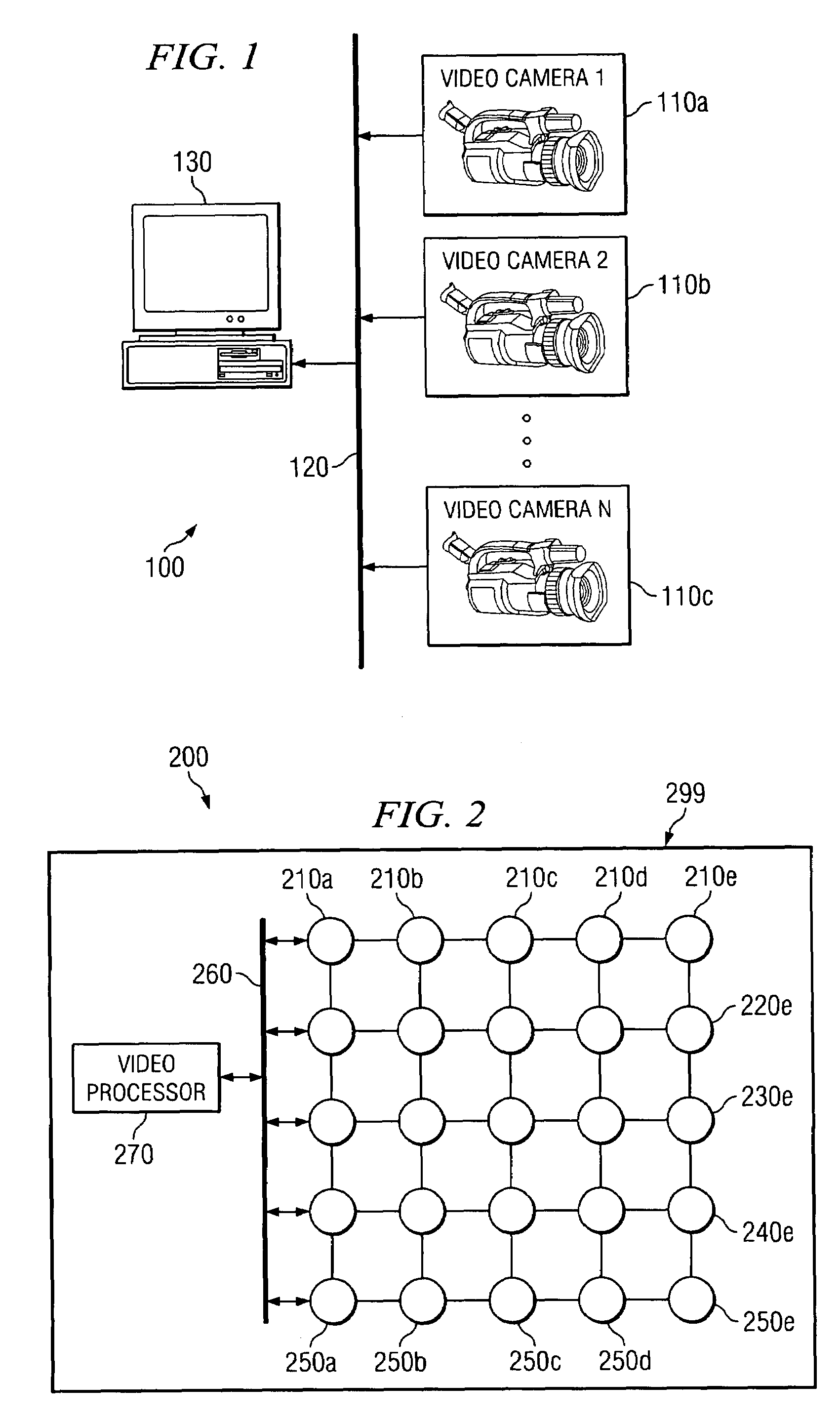
[0030]FIG. 1 illustrates compound camera system 100 according to a first exemplary embodiment of the present invention. Compound camera system 100 comprises N component video cameras 110, including exemplary component video cameras 110a, 110b, and 110c, and processing system 130. Component video came...


PUM


Abstract

A compound camera system for generating an enhanced virtual image having a large depth-of-field. The compound camera system comprises a plurality of component cameras for generating image data of an object and a data processor for generating the enhanced virtual image from the image data. The data processor generates the enhanced virtual image by generating a first component virtual image at a first depth plane, generating a second component virtual image at a second depth plane, and inserting first selected pixels from the first component virtual image into enhanced the virtual image and inserting second selected pixels from the second component virtual image into the enhanced virtual image.

Description

CROSS-REFERENCE TO RELATED APPLICATIONS[0001]The present invention is related to those disclosed in U.S. patent application Ser. No. 10 / 407,505, filed concurrently herewith, entitled “Compound Camera and Method for Synthesizing a Virtual Image From Multiple Input Images.” Application Ser. No. 10 / 407,505 is commonly assigned to the assignee of the present invention. The disclosures of this related patent application is hereby incorporated by reference for all purposes as if fully set forth herein.TECHNICAL FIELD OF THE INVENTION[0002]The present invention is generally directed to image processing devices and, in particular, to a compound camera that generates virtual images from a plurality of input images captured by the compound camera.BACKGROUND OF THE INVENTION[0003]A compound camera consists of a set of component cameras, a data processor and image processing software that runs on the data processor. The component cameras may be synchronized through wired or wireless electronic ...

Claims


Application Information

Patent Timeline
Patent Type & Authority Patents(United States)
IPC IPC(8): H04N7/18H04N5/225H04N5/262G03B15/00G06T5/50G06T15/20G06V10/147H04N5/232
CPCG06K9/209G06T15/20H04N5/247H04N5/23232G06T2207/10052G06T2200/21G06V10/147H04N23/951H04N23/90
Inventor CHEN, GEORGE Q.HONG, LIMCGUINNESS, PETER
Owner STMICROELECTRONICS SRL
Why Eureka
Try Eureka