Method of forming a three-dimensional image of a pattern to be inspected and apparatus for performing the same

a three-dimensional image and pattern technology, applied in the direction of instruments, semiconductor/solid-state device testing/measurement, nuclear engineering, etc., can solve the problems of large time expenditure, sample pattern to be broken down through destructive analysis, and difficulty in measuring defects, etc., to achieve the effect of easy detection

Active Publication Date: 2008-09-23
SAMSUNG ELECTRONICS CO LTD
View PDF4 Cites 7 Cited by
  • Summary
  • Abstract
  • Description
  • Claims
  • Application Information

AI Technical Summary

Benefits of technology

[0013]According to the present invention, various three-dimensional images for various inspection patterns are obtained through an iterative process without fracturing the substrate and using an X-ray that is utilized for detecting a layer thickness or a concentration of a particular element of the layer. Accordingly, types and locations of the defects in the inspection pattern may be easily detected through the three-dimensional image of the inspection pattern.

Problems solved by technology

However, the scaling down of the critical dimension leads to difficulty in measuring the defects.
However, they also have a disadvantage in that a sample pattern is required for the implementation of these microscopes and thereby requires the sample pattern to be broken down through a destructive analysis.
Furthermore, the use of V-SEM and TEM require large expenditures of time to achieve the analysis.
That is, the use of V-SEM and the TEM are problematic in that the specimen for the analysis is broken down (e.g., is fractured) and is disposed of after the analysis.
Recently, an optical method has been introduced for this type of analysis; however, the method is problematic in that the process and calculation on processing data are very complicated and too cumbersome to apply to a practical analysis on the vertical pattern profile.

Method used


Image

  • Method of forming a three-dimensional image of a pattern to be inspected and apparatus for performing the same
  • Method of forming a three-dimensional image of a pattern to be inspected and apparatus for performing the same
  • Method of forming a three-dimensional image of a pattern to be inspected and apparatus for performing the same

Examples


Embodiment Construction

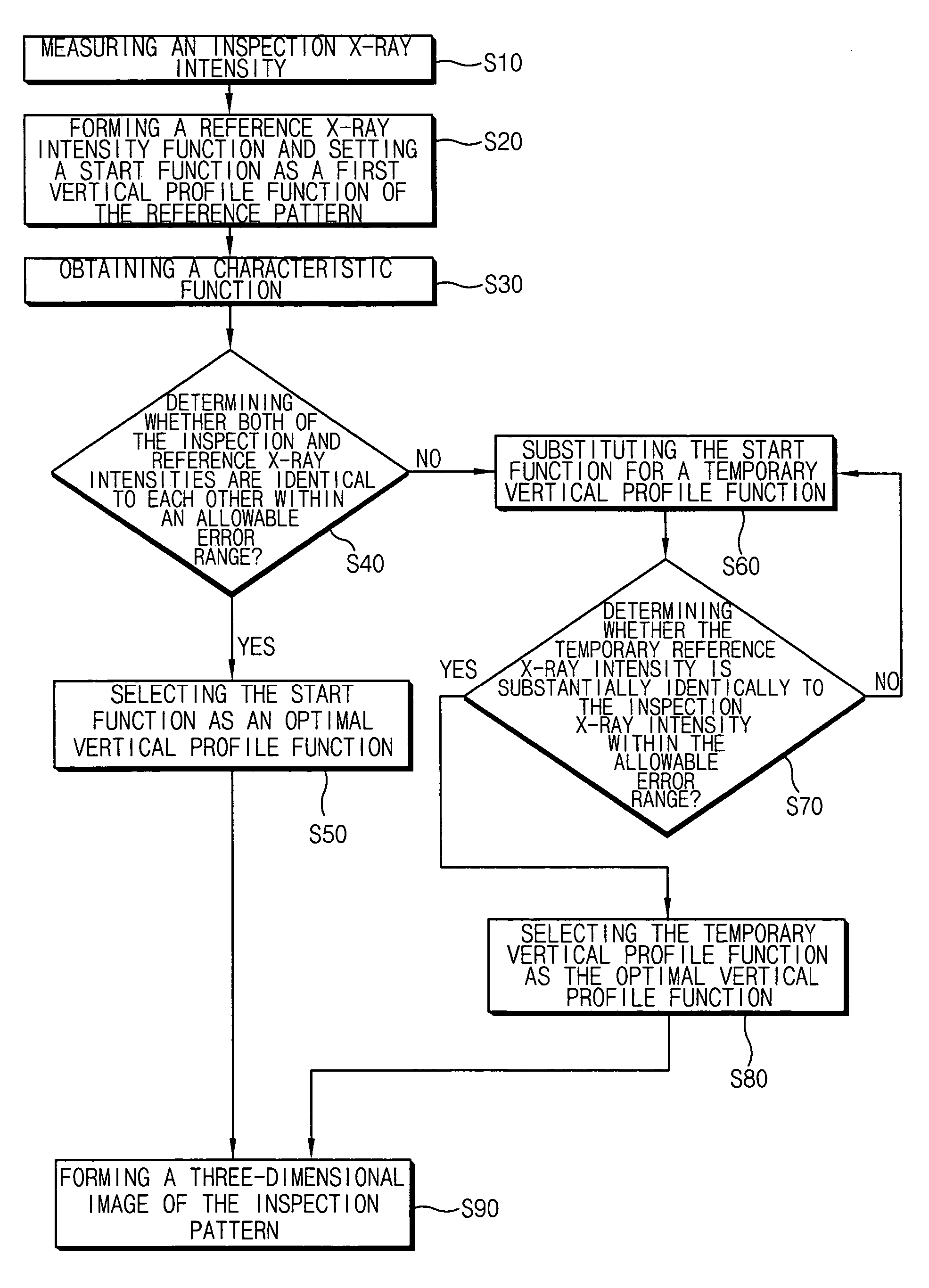
[0025]The present invention now will be described more fully hereinafter with reference to the accompanying drawings in which exemplary embodiments of the present invention are shown.

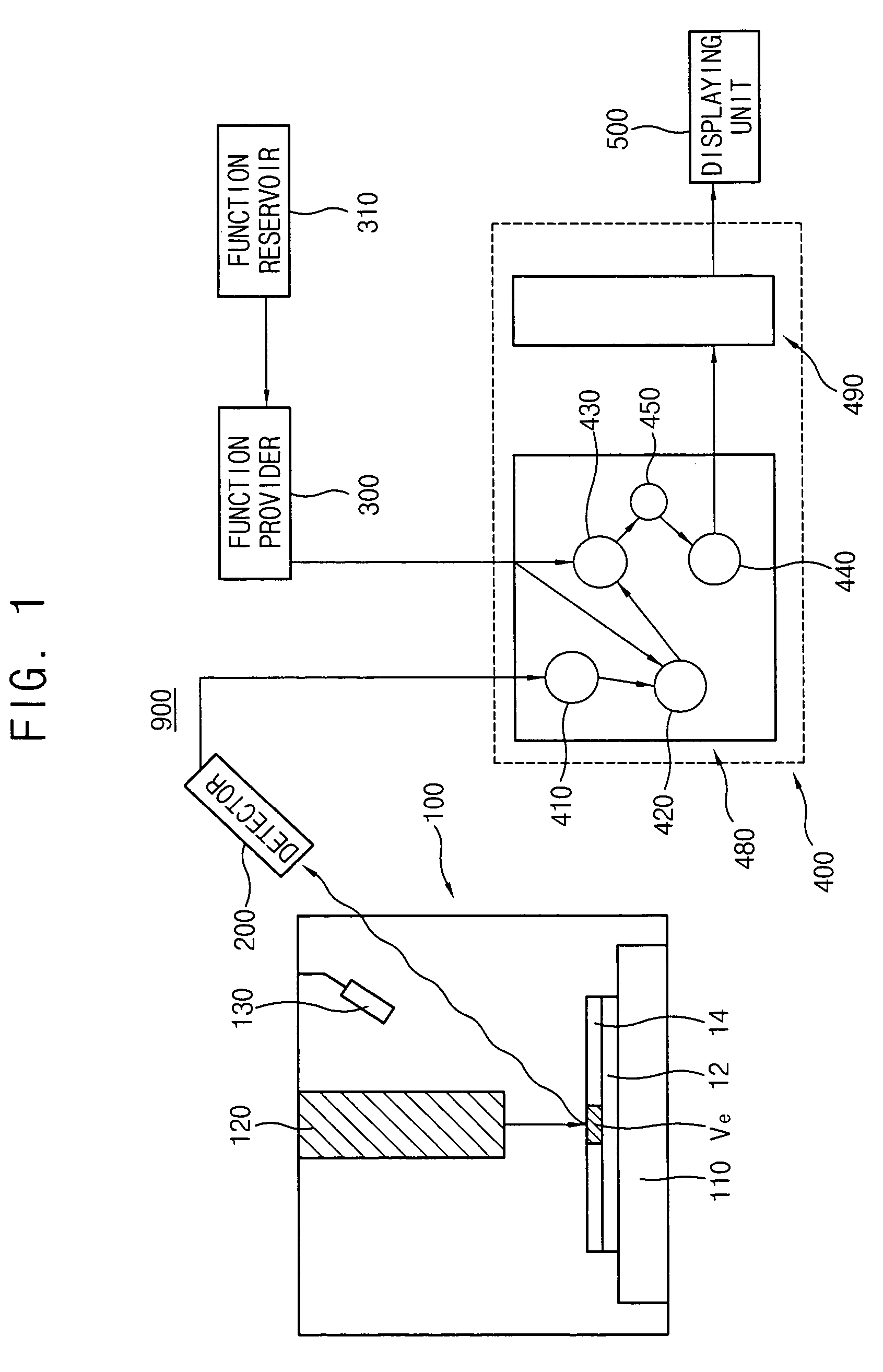
[0026]FIG. 1 is a view illustrating an apparatus for forming a three-dimensional image of an inspection pattern according to an exemplary embodiment of the present invention.

[0027]Referring to FIG. 1, an apparatus 900 for forming a three-dimensional image includes a generator 100 for generating an electromagnetic wave, a detector 200 for detecting the electromagnetic wave generated from the generator 100, a function provider 300 for providing a vertical profile function of a reference pattern and a profile generator 400 for generating a three-dimensional profile of the inspection pattern. The generator 100 generates the electromagnetic wave from an object (not shown) including the inspection pattern and from a reference specimen (not shown) including the reference pattern, respectively. The vertical pro...


PUM


Abstract

In a method and apparatus for forming a three-dimensional image for an inspection pattern, a reference intensity function of an inspection X-ray is formed in accordance with a continuous scanning depth, and is differentiated with respect to the scanning depth. The differential reference intensity function is decomposed into a start function and a characteristic function. The differential reference intensity function is then repeatedly integrated while a temporary vertical profile function is substituted for the start function until the temporary intensity of a reference X-ray is within an allowable error range. The temporary vertical profile function satisfying the error range is selected as an optimal vertical profile function. A surface shape is combined to the optimal vertical profile function along a depth of the inspection pattern to thereby form the three-dimensional image for the inspection pattern.

Description

CROSS-REFERENCE TO RELATED APPLICATION[0001]This application relies for priority upon Korean Patent Application No. 2004-54562 filed on Jul. 13, 2004, the content of which is herein incorporated by reference in its entirety.BACKGROUND OF THE INVENTION[0002]1. Field of the Invention[0003]The present invention relates to a method and an apparatus for forming a three-dimensional image of a pattern to be inspected, and more particularly, to a method of forming a three-dimensional image of a pattern using X-rays without fracturing the pattern.[0004]2. Description of the Related Art[0005]As semiconductor devices are becoming highly integrated and are operating at higher speeds, design rule requirements and contact areas of the devices are being continuously reduced. This reduction has lead to requirements to form a finer pattern and a smaller contact hole on the pattern. The fine pattern and smaller contact hole require an improved measuring technology for detecting a critical dimension o...

Claims


Application Information

Patent Timeline
Patent Type & Authority Patents(United States)
IPC IPC(8): G06K9/00
CPCG21K7/00H01L22/00
Inventor JEE, YUN-JUNGJUN, CHUNG-SAMYANG, YU-SINKIM, TAE-KYOUNG
Owner SAMSUNG ELECTRONICS CO LTD
Why Eureka
Try Eureka