Valve assembly having articulating rigid seating surface

a valve assembly and seating surface technology, applied in the direction of valve operating means/releasing devices, mechanical equipment, transportation and packaging, etc., can solve the problems of increased manufacturing costs of valve assemblies, deformation of sealing, and labor intensiv

Active Publication Date: 2008-09-30
MKS INSTR INC
View PDF10 Cites 14 Cited by
  • Summary
  • Abstract
  • Description
  • Claims
  • Application Information

AI Technical Summary

Benefits of technology

[0007]The present disclosure provides a valve assembly including a valve body having an orifice, and a valve member received in the valve body and movable along an axis with respect to the orifice. The valve member includes a cup in an end of the valve member and the cup has an end wall facing the orifice of the valve body. A fulcrum extends from the end wall of the cup towards the orifice, and a plug is received in the cup against the fulcrum and opposite the orifice of the valve body. When the valve member is moved along the axis towards the orifice, the plug contacts the valve body to seal the orifice. The valve assembly also includes a flat spring having an outer portion secured to the end of the valve member and flexible arms retaining the plug in the cup so that the plug can be articulated about the fulcrum and properly aligned with the valve body to fully seal the orifice when the valve member is moved along the axis towards the orifice.
[0008]Among other benefits and aspects of the present disclosure, the articulating plug of the valve assembly ensures that seating surfaces of the plug and the valve body will be properly aligned when the valve member is moved towards the orifice to seal the orifice, such that the valve assembly provides improved cut-off sealing. The articulating plug eliminates the need for hand-crafted metal parts and allows the use of impervious non-metal material, such as sapphire, for the seating surfaces. Sapphire seating surfaces, in turn, provide stable, long-term control valve shut-off capability.

Problems solved by technology

Such lapping operations however, are labor intensive and increase the manufacturing costs of the valve assemblies.
In addition, metal-lapped surfaces can be attacked at high temperatures by corrosive fluids, which degrade sealing over time.

Method used


Image

  • Valve assembly having articulating rigid seating surface
  • Valve assembly having articulating rigid seating surface
  • Valve assembly having articulating rigid seating surface

Examples


Embodiment Construction

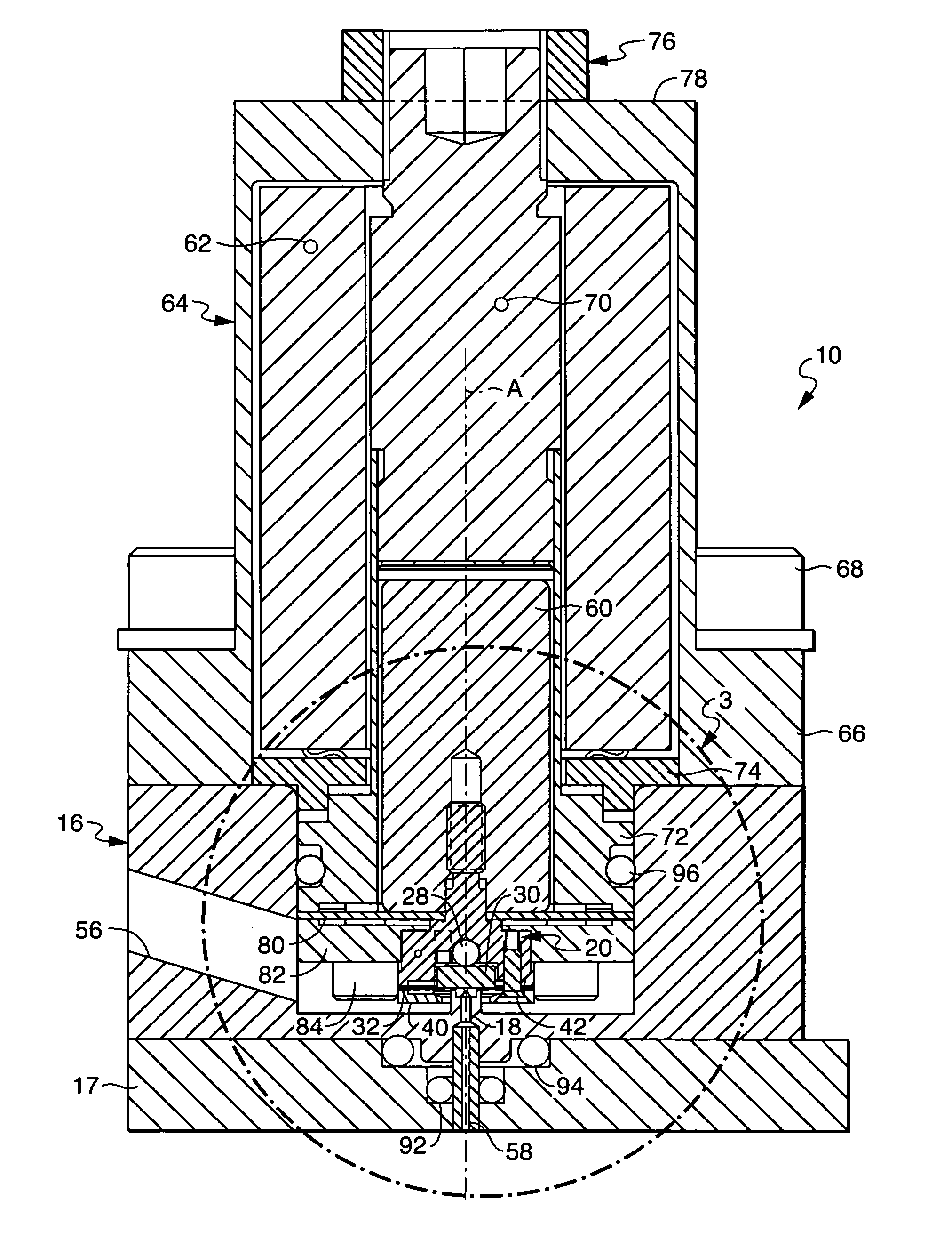
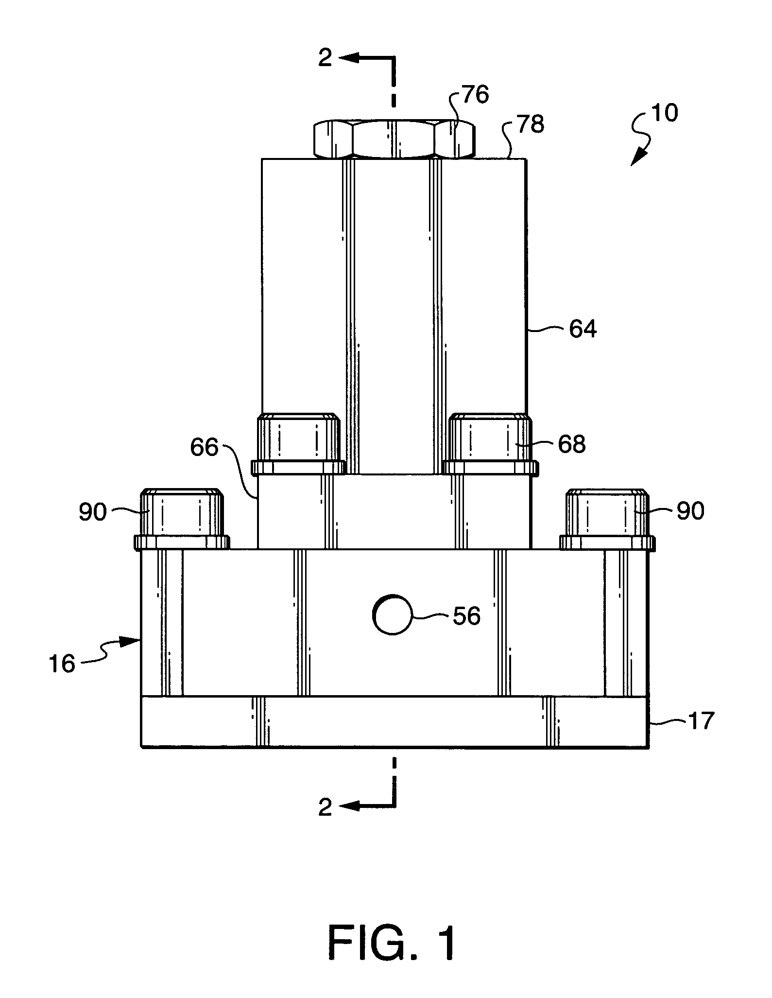
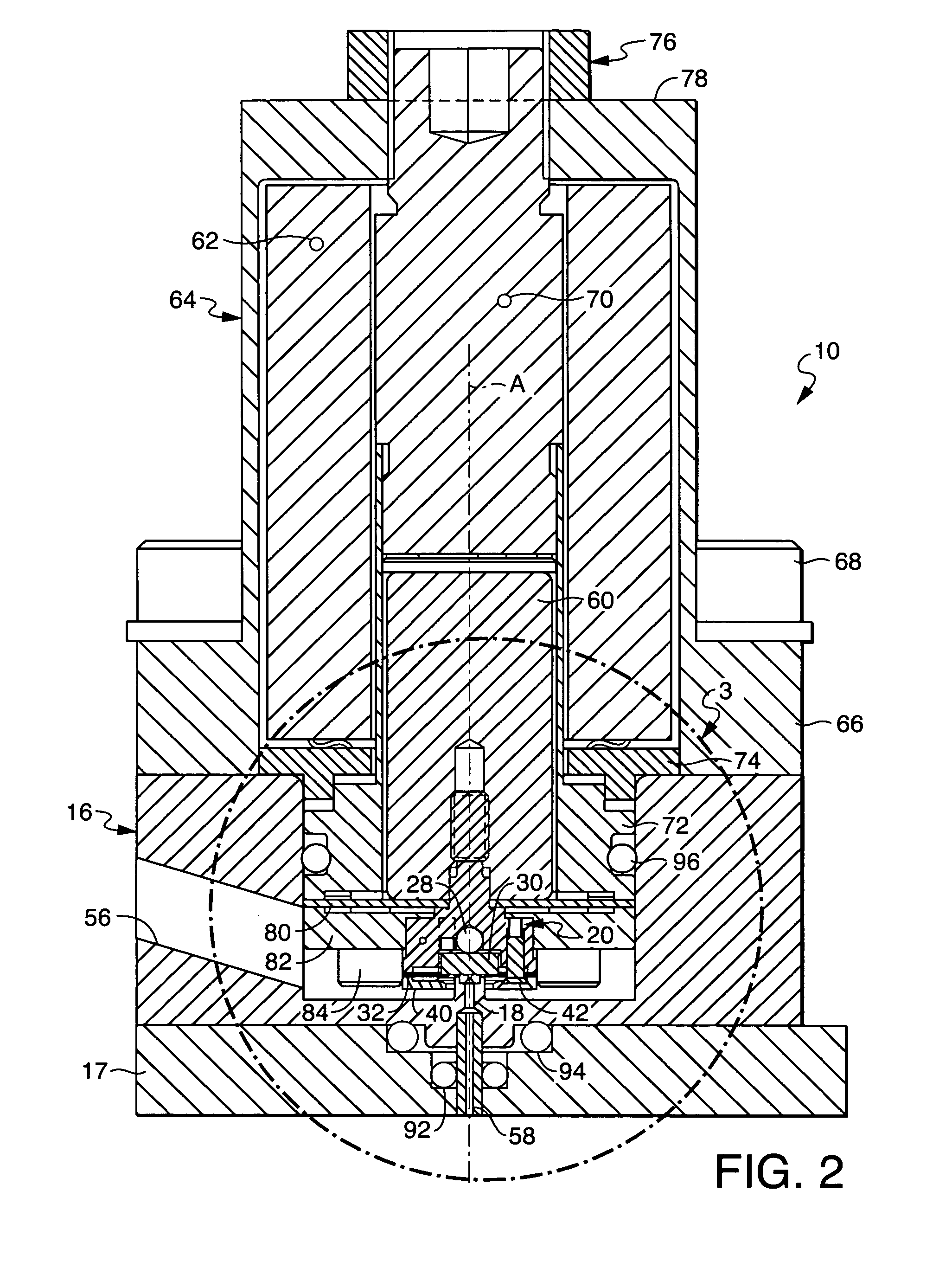
[0021]Referring to FIGS. 1 through 9, the present disclosure generally provides a valve assembly 10 that includes sapphire seating surfaces 12, 14, which are shown best in FIGS. 3 and 4. The novel design of the valve assembly 10 of the present disclosure allows at least one of the seating surfaces to be articulated, or toggled, so that the seating surfaces 12, 14, which are planar, are automatically made parallel during use. The parallel condition of the planar seating surfaces 12, 14 ensure that the seating surfaces provide improved cut-off sealing. In addition, the use of sapphire seating surfaces 12, 14 eliminates the need for hand-crafted metal parts, and provides stable long term control valve shut-off capability (i.e., no degradation of the seating surfaces 12, 14).

[0022]Referring to FIGS. 2 through 4, the valve assembly 10 includes a valve body 16 having an orifice 52 positioned over a passageway 18, and a valve member 20 received in the valve body 16 and movable along an axi...


PUM


Abstract

A valve assembly including a valve body having an orifice, and a valve member received in the valve body and movable along an axis with respect to the orifice. The valve member includes a cup in an end of the valve member and the cup has an end wall facing the orifice of the valve body. A fulcrum extends from the end wall of the cup towards the orifice, and a plug is received in the cup against the fulcrum and opposite the orifice of the valve body. When the valve member is moved along the axis towards the orifice, the plug contacts the valve body to seal the orifice. The valve assembly also includes a flat spring having an outer portion secured to the end of the valve member and flexible arms retaining the plug in the cup, so that the plug can be articulated about the fulcrum and properly aligned with the valve body to fully seal the orifice when the valve member is moved along the axis towards the orifice.

Description

FIELD OF THE DISCLOSURE[0001]The present disclosure relates to the field of fluid flow control and, more particularly, to a valve assembly. Even more particularly, the present disclosure relates to a valve assembly having rigid seating surfaces, and wherein at least one of the rigid seating surfaces articulates to ensure a suitable seal.BACKGROUND OF THE DISCLOSURE[0002]Fluid valves exist in a wide variety of forms and sizes, serving a multitude of purposes, handling flowable materials whose characters range from light gaseous to heavy slurries and near-solids, and operable at various speeds under controls as diverse as simple binary (ON-OFF), proportional, direct-manual and remote-electrical. Those which are capable of responding quickly to govern even relatively large flows with precision, and with expenditure of little electrical power, are of special interest in certain industrial processing, such as the automatic regulation of gases in semiconductor and integrated-circuit manuf...

Claims


Application Information

Patent Timeline
Patent Type & Authority Patents(United States)
IPC IPC(8): F16K31/04
CPCF16K1/36F16K31/0655F16K25/005F16K1/42Y10T137/7761F16K25/00
Inventor BENSON, RICHARD A.
Owner MKS INSTR INC
Why Eureka
Try Eureka