Simplified filter device

A filter device and filter plate technology, applied in the direction of filtration separation, fixed filter element filter, electrodialysis, etc., can solve problems such as inability to evaluate, and achieve the effects of easy assembly/disassembly, prevention of leakage and mixing, and simple structure

Inactive Publication Date: 2006-09-13
ENTEGRIS INC
View PDF0 Cites 8 Cited by
  • Summary
  • Abstract
  • Description
  • Claims
  • Application Information

AI Technical Summary

Problems solved by technology

However, there is a problem in that, in the case of using multiple separation membranes in series, even this device cannot evaluate them

Method used


Image

  • Simplified filter device
  • Simplified filter device
  • Simplified filter device

Examples


no. 1 example

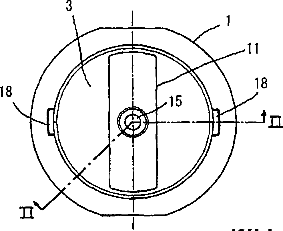
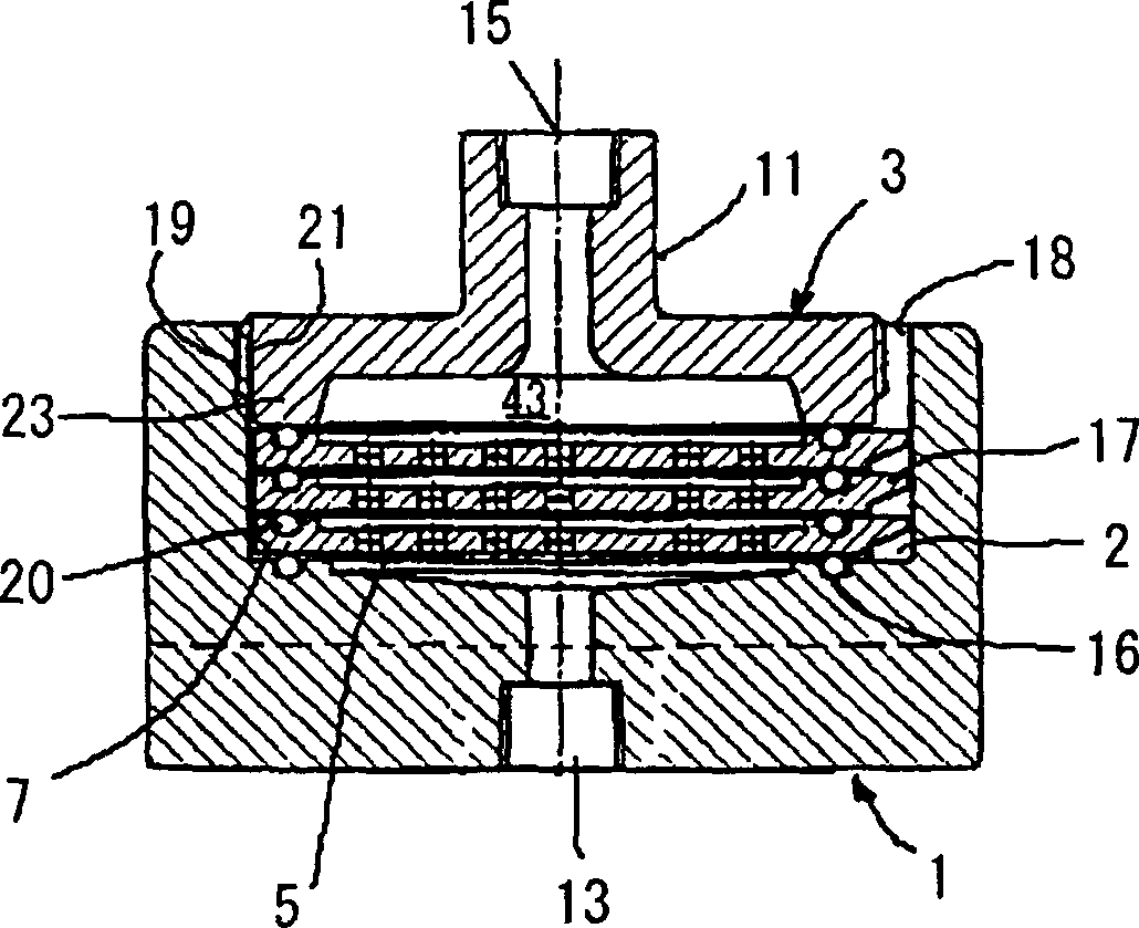
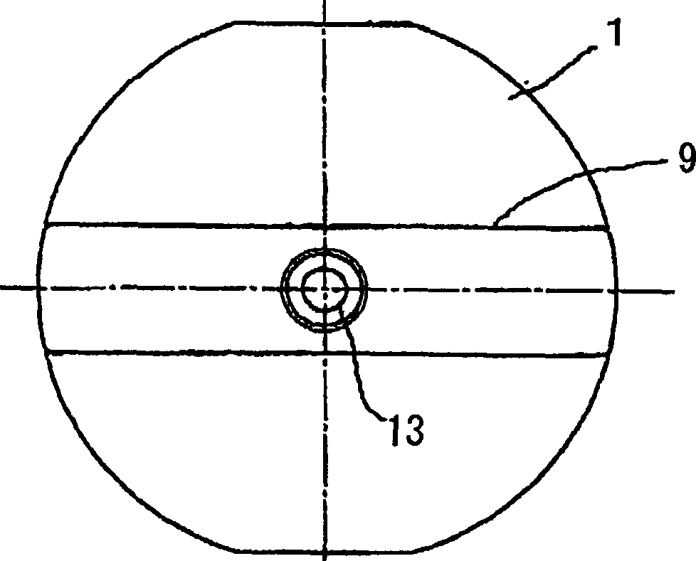
[0118] The following will refer to Figures 1 to 7 A simplified filter device of the first embodiment of the present invention is explained. The vertical relationship between the various parts of each figure depends on the convenience of relative interpretation. That is, the vertical relationship thereof may be reversed, or may be arranged horizontally, or the raw liquid supply port and the filtered liquid discharge port may be reversed from each other.

[0119] When referring to Figures 1 to 6 and yes figure 2 part of enlarged view of Figure 7 , the filtering device includes a bowl (or cup) 1, with a discharge port 13 on its lower surface, the filtered liquid is discharged from the discharge port, and an opening (or recess) 2 on its upper surface, one or more The filter plate 5 is inserted into the opening part 2, and is supported by the bottom of the opening part; the filter device also includes a head 3, which has a protruding pressurized part 23 shaped like a ring, ...

no. 2 example

[0127] Refer below Figures 8 to 14 A second embodiment of the present invention is explained. Although this embodiment is more complicated than the filter unit of the previous embodiment, it has the advantage that airtightness and liquidtightness are easily obtained. In each of these related figures, the same reference numerals are used for those components corresponding to those of the filter device of the first embodiment.

[0128] The filter device according to this embodiment includes a bowl 1 having a discharge port 13 on the lower surface of the bowl 1 through which the filtered liquid is discharged, and the bowl 1 has an opening portion or a recess on its upper surface 2. One or more filter plates 5 are inserted into the opening part 2, and are supported by the bottom of the opening part; the filter device also includes a head 3, which has a protruding pressurized part 23 shaped like a ring, and the head 3 will filter The peripheral portion of the plate 5 is pressuri...

no. 3 example

[0136] A third embodiment of the present invention is explained below with reference to FIGS. 15 to 23. FIG. Although this example is similar to the reference Figures 8 to 14 The second embodiment explained, but the difference lies in the structure of the sealing part of the filter plate, the structure of the finger grip part of the filter plate and the structure of the lock nut. Of course, in each of these drawings, those components corresponding to those of the filtering device of the second embodiment are denoted by the same reference numerals.

[0137] Figure 15 is a perspective view of the filter device according to this embodiment, Figure 16It is a cross-sectional view taken along line XVI-XVI in FIG. 15 . The filter device of this embodiment comprises a bowl 1 having an opening portion or recess 2 and a discharge port 13 for discharging the filtered liquid; one or more filter plates 5 inserted in the opening portion 2, and Supported by the bottom of the opening por...


PUM


Abstract

A flow passage for passing a raw liquid to be processed therethrough that is used to test a separation membrane is of the simplest inline type (so-called 'inline' type) and is the simplest in construction. In spite thereof, the separation membrane through which the raw liquid is going to be filtered is mounted in a direction substantially perpendicular to the flow passage. In view of this, the object of the present invention is to provide a filtering device with high filtering efficiency, which is used to test the membrane performance of this separation membrane and which enables exchanging its membrane in an easily removably attachable and quick way. The simplified type filtering device that includes a bowl 1 having a discharging port 13 on one side thereof and having on the other side thereof an opening portion 2 in which the separation membrane is loaded, the separation membrane for filtering the raw liquid therethrough, a filter plate 5 by which this separation membrane is fixed to the bowl 1 and which has opening portions for passing the raw liquid or a filtered liquid therethrough, a head 3 having on one side thereof a convex pressing portion 23 that presses the filter plate 5 from one side to prevent the filtered liquid from being leaked and having on the other side thereof a raw liquid supplying opening 15, and means that fastens the head 3 onto the bowl 1 so that the head may be pressed against the bowl 1, such as female and male screws 19, 21 provided with respect to the head 3 and the bowl 1 and screw-engaged with each other, or a separate locking nut 33.

Description

technical field [0001] The present invention relates to a kind of filter device, it can be used as filter to filter, separate or extract gel and other particle etc. from liquid, can test the filter membrane that this filter uses, separation membrane or purification membrane (hereinafter referred to as "Separation Membrane") Membrane Properties. [0002] The filtering device of the present invention is widely used for filtering a small amount of substances in order to conduct research and development, develop resists, develop medicines, make beer, make medicines, purify photoresist solutions in the process of manufacturing semiconductors or other fields. Background technique [0003] There is a great demand for filtration devices for filtering, separating and purifying small quantities of raw liquid supplied. Moreover, in order to judge whether the separation membrane is most suitable for the liquid to be treated, it is necessary to process the liquid to be treated by actual...

Claims


Application Information

Patent Timeline
Patent Type & Authority Applications(China)
IPC IPC(8): B01D63/08B01D61/50B01D29/05
Inventor 须藤和德冈荣子
Owner ENTEGRIS INC
Why Eureka
Try Eureka