Method for operating a tool shaft

a technology of tool shaft and tool shaft, which is applied in the direction of mechanical measuring arrangement, instruments, and using mechanical means, etc., can solve the problems of sensor loss of sensitivity and tedious recalibration

Active Publication Date: 2008-10-07
PRIAMUS SYST TECH AG
View PDF9 Cites 12 Cited by
  • Summary
  • Abstract
  • Description
  • Claims
  • Application Information

AI Technical Summary

Benefits of technology

[0008]This method according to the invention has the major advantage that no force secondary-path effect occurs in which the sensor element touches the tool internal wall, in consequence significantly adversely affecting or entirely losing its sensitivity. The quality of the hole in the tool wall can now be ignored. The only important factor is the quality of the hole in the sleeve. However, it is cheaper and easier to produce a high-quality hole in the sleeve than to produce such a hole in the tool wall. Normally, the production of high-quality holes can be left to the manufacturer of these sensor sleeves.
[0011]If the sensor element is arranged with a small amount of play in the sleeve, it can move freely in one preferred direction. The sensor element play can in this case be chosen such that, on the one hand, free mobility is ensured while, on the other hand, any ingress of a medium between the sensor element and the sleeve is minimized.
[0013]A further advantage of guidance in the sleeve is that the variable to be measured can be channelized to the point intended for this purpose. For example, the sensor element can thus be arranged in a sleeve in such a way that pressure acts on the sensor element from only one specific direction. This makes it possible to prevent and / or reduce measurement corruption.
[0014]The sleeve is preferably placed on a base body of the sensor, from which the sensor element also projects. This makes it possible to achieve a very robust arrangement, in which the sensor can be arranged physically simply and at low cost in the protective apparatus. The sensitivity and the sensitivity range of the sensor are thus fixed before its installation, and these parameters of the sensor need not be defined after its installation.
[0015]A fixed connection of the sleeve and base body makes the arrangement of the entire apparatus more robust. A connection by means of welding or adhesive bonding is particularly simple. If a releasable connection is desired, the sensor can also be screwed in the sleeve.
[0016]In one preferred refinement, the sensor element has an annular groove for holding a seal. The seal prevents the ingress of the medium between the sleeve and the sensor element, which could reduce the play between the sleeve and the sensor element meaning that the sensor element could not move with respect to the sleeve.

Problems solved by technology

This force secondary-path effect can result in the sensor losing sensitivity, which necessitates tedious recalibration of the measurement system.

Method used


Image

  • Method for operating a tool shaft
  • Method for operating a tool shaft
  • Method for operating a tool shaft

Examples


Embodiment Construction

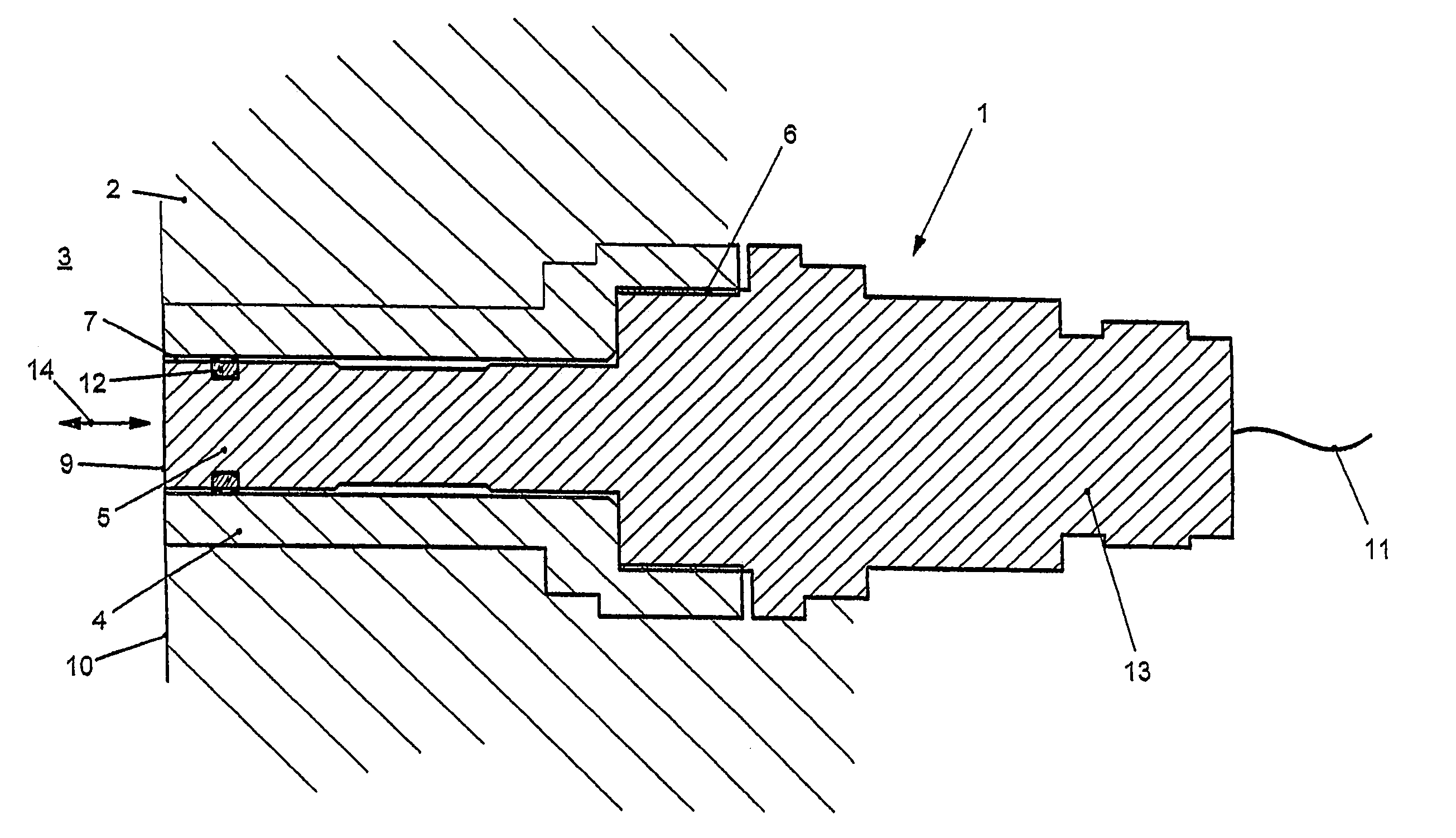
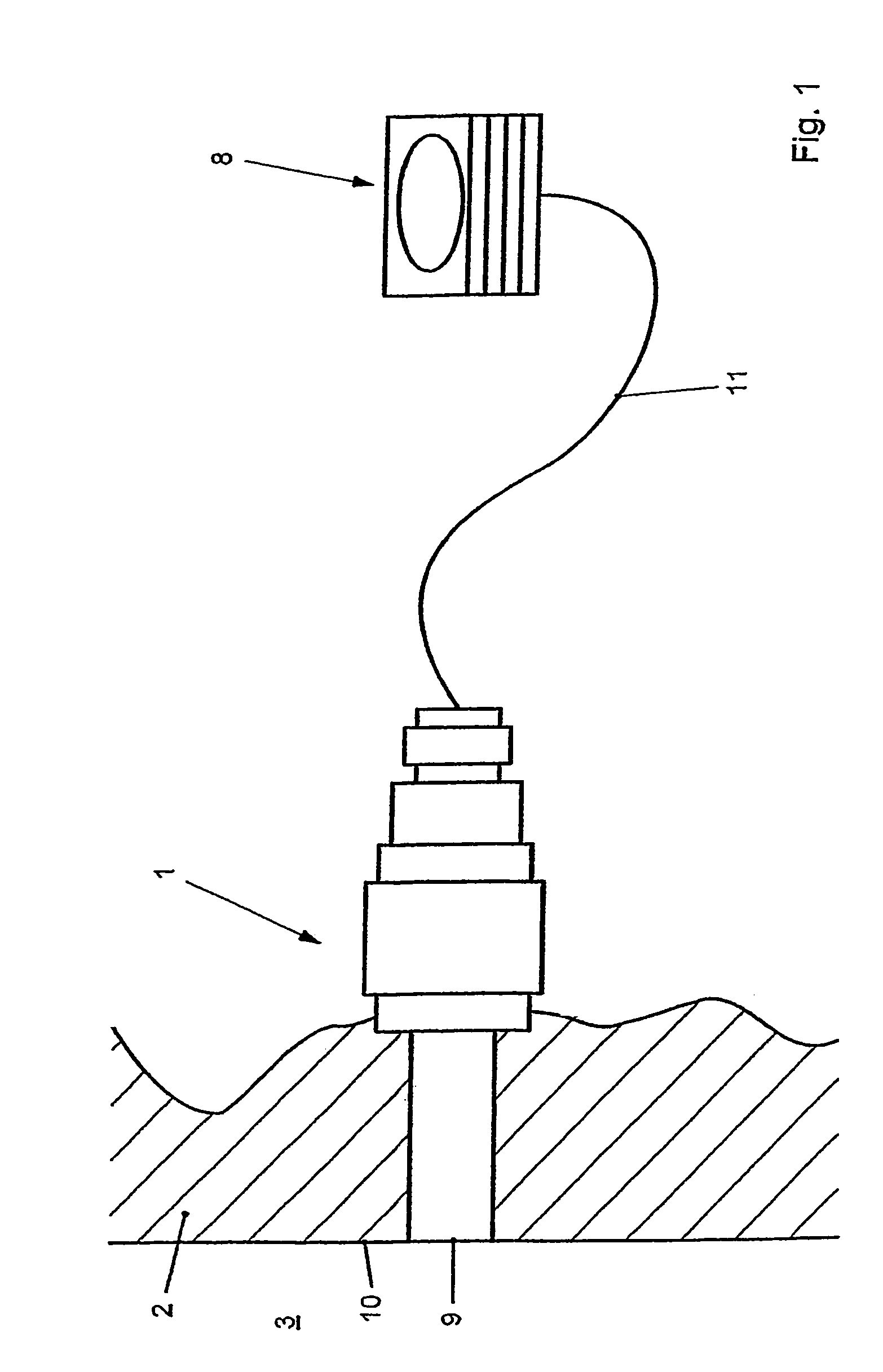
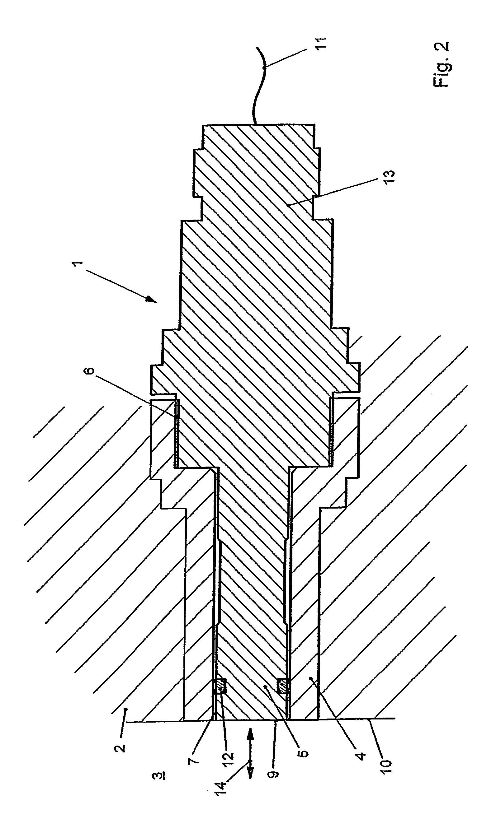
[0020]FIG. 1 shows a sensor 1, which is arranged in a hole in a wall 2 of a cavity 3 in an injection-molding or die-casting tool. The sensor 1 is used, for example, to measure the tool internal pressure in the cavity 3. In this case, one end wall 9 of the sensor 1 is arranged on the same plane as one internal surface 10 of the wall 2, such that it is subject to the influence of a melt entering the cavity 3.

[0021]The measured variable, for example the tool internal pressure, can be converted by the sensor 1 in particular to an electrical signal and can be passed on via a cable 11 to an evaluation unit 8, which can monitor and control the entire process. For example, this arrangement can be used in particular to determine the time to change from the filling pressure to the subsequent pressure. At this point, it should be noted that the measured variable can also be transmitted cordlessly. Transmission by other than electrical means, for example optical transmission, is also feasible.

[...


PUM

PropertyMeasurementUnit
pressureaaaaaaaaaa
physicalaaaaaaaaaa
physical characteristicsaaaaaaaaaa

Abstract

A method for operating a tool shaft with the aid of a sensor element of a sensor, particularly an injection mold, in which at least one sensor, e.g. for determining an internal pressure of the mold, is assigned to the cavity. To this end, the sensor element is placed inside a sleeve with play and is subsequently calibrated, then, after determining the sensitivity, a correspondingly codeable component, e.g. a resistor, is selected, is fitted into the sensor, and the sensor, together with the sleeve, is placed inside a borehole of a mold wall.

Description

[0001]The invention relates to a method for operation of a tool shaft with the aid of a sensor element of a sensor, in particular of an injection-molding or die-casting tool, in which the cavity has at least one associated sensor, for example for determination of a tool internal pressure and the sensor element is inserted into a sleeve with play.PRIOR ART[0002]Sensors for an indefinitively large number of technical fields are known from the prior art, where they are used to measure physical variables. The measured physical variables may, for example, be input parameters for a controller which, in particular, accompanies and controls a production process. By way of example, it is thus possible to monitor the physical characteristics of an element to be produced during production and, if necessary, to modify appropriate parameters. For this purpose, the sensors may be in contact with the element to be produced or with the material forming the element. In order to avoid measurement cor...

Claims


Application Information

Patent Timeline
Patent Type & Authority Patents(United States)
IPC IPC(8): G01N3/02B29C45/77G01D11/30G01L19/00
CPCB29C45/77G01D11/30G01L19/0007G01L19/00
Inventor BADER, CHRISTOPHERUS
Owner PRIAMUS SYST TECH AG
Why Eureka
Try Eureka