Modular downlight assembly

a module and assembly technology, applied in fixed installation, lighting and heating apparatus, lighting support devices, etc., can solve the problems of not teaching the concept of modularity, not adequately restricting pivotal movement, miles not teaching any means built in a downlight assembly, etc., to prevent excessive relative movement and improve synchronous movement and stabilization of links

Active Publication Date: 2008-10-07
WAC LIGHTING
View PDF16 Cites 107 Cited by
  • Summary
  • Abstract
  • Description
  • Claims
  • Application Information

AI Technical Summary

Benefits of technology

[0006]An object of the invention is to provide a modular downlight assembly enabling a selected variable number of essentially similar downlight assemblies to be mounted in or removed from a single back housing by ready access from below, permitting the selective addition and removal of individual downlight assemblies while the back housing remains mounted in the ceiling cavity.
[0008]An additional object of the invention is to incorporate angular scales or protractors in each individual modular downlight assembly to enable the user to readily select a precise angular position of rotation for the lamp.
[0024]A link of one chain intersects and is pivotally connected to a link of the other chain for improved synchronous movement and stabilization of the linkages.
[0025]Two similar dual linkages may extend between the lamp holder housing and the mounting plate, each dual linkage extending on an opposite side of the lamp holder from the other and the lowermost link may be formed with a motion limiting flange which protrudes into the path of pivotal movement of the lamp holder housing thereby to limit the pivotal movement of the lamp holder housing. Additionally, selected motion limiting flanges may be provided on selected links of respective chains to prevent excessive relative movement thereof.
[0027]The perimeter of the turntable may be provided with eccentric stop surfaces aligned for engagement with stop pins staked in the mounting plate to limit rotation of the turntable to prevent damage to the lamp lead.
[0029]The plate-form turntable may comprise rotation controlling means comprising a perimetrically toothed annulus and a tooth engaging detent mounted cooperatively on an upper face of the mounting plate and joined though the mounting plate to the lower plate, so that the detent successively engages and releases successive teeth during rotation to provide a tensioning effect and enable precise, incremental rotational positioning of the lamp.

Problems solved by technology

However, Miles does not teach the concept of modularity enabling any selected variable number of closely similar downlight assemblies to be mounted in a single back housing in a ceiling cavity or, means permitting the selective addition and removal of a downlight assembly by ready access only from below the ceiling while the back housing remains mounted in the ceiling cavity.
Furthermore, Miles does not teach any means built in a downlight assembly for determining a precise angle of rotation about the vertical or horizontal axes for ease of aiming adjustment and calibration, nor for adequately limiting the pivotal movement of the lamp holder housing independently of engagement with the back housing or cabling.

Method used


Image

  • Modular downlight assembly
  • Modular downlight assembly
  • Modular downlight assembly

Examples


Embodiment Construction

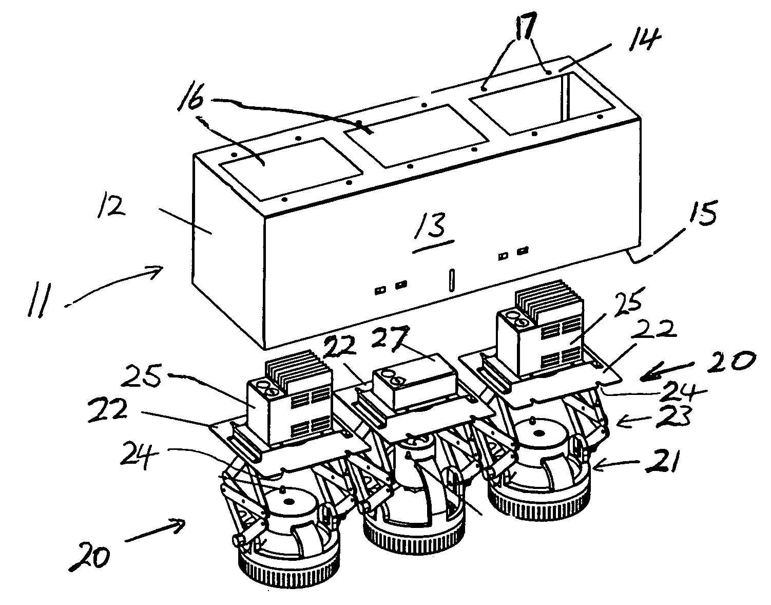
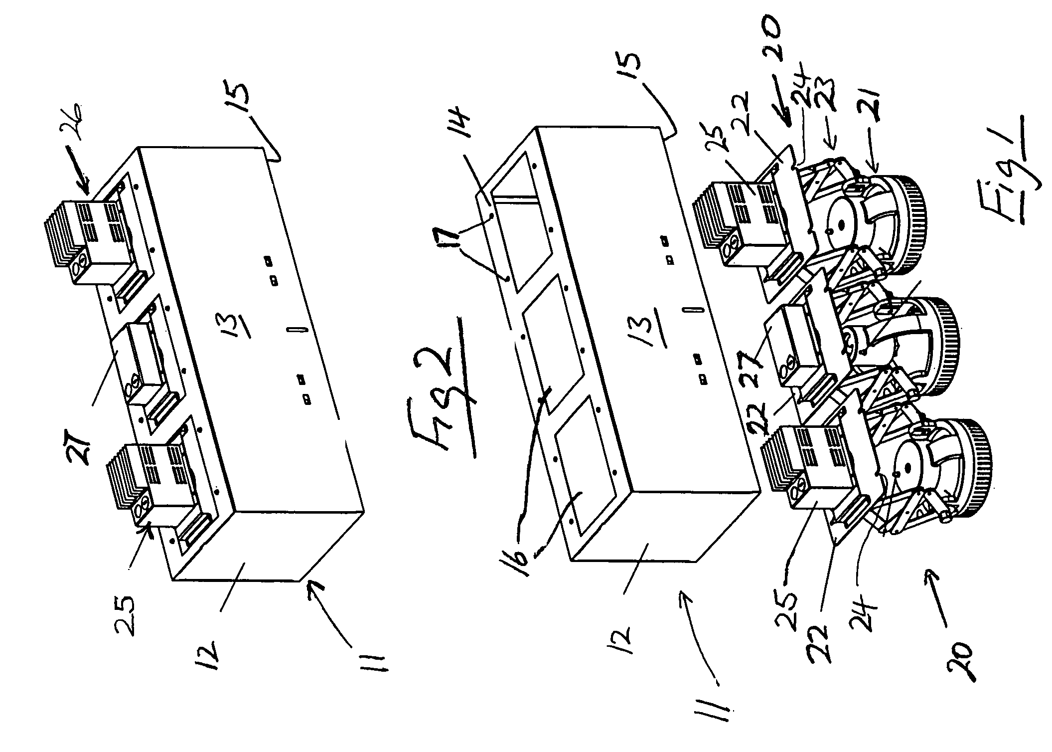
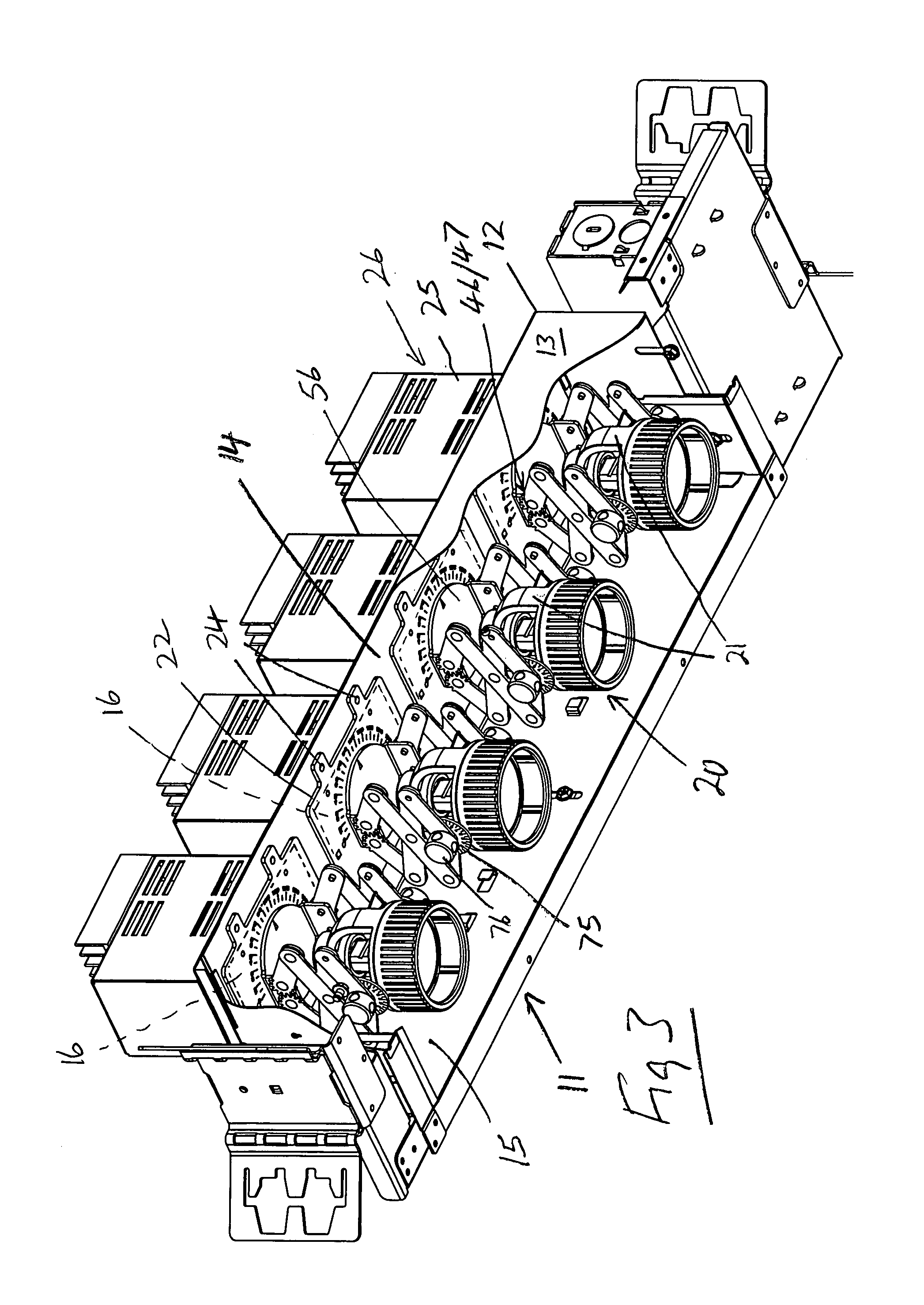
[0044]As shown in FIGS. 1-4, a modular downlight assembly comprises a back housing 11 having a frame 12 of inverted channel section with opposite sidewalls 13 extending downwards from opposite sides of a channel base wall 14 so that free, lower ends of the sidewalls define a channel mouth 15 for mounting in a cavity (not shown) formed in a ceiling or dropped ceiling with the sidewalls and base concealed / recessed within the cavity and the channel mouth opening to below the ceiling cavity. A plurality of apertures 16 of a same size as each other are formed in the base wall 14 for receiving, respectively, selected individual downlight modules 20 while the back housing 11 is mounted in the cavity. The base wall 14 has respective down light module attachment / fastening means 17 (screw holes) at a same location for each aperture 16.

[0045]A plurality of downlight modules 20 each comprises a lamp holder housing 21 suspended from a lower face of a mounting plate 22 by an extensible scissor / to...


PUM


Abstract

A modular downlight assembly having a channel shaped back housing for mounting in a ceiling cavity and formed with a series of identical apertures receiving, respectively, when mounted in the cavity, selected similar individual downlight modules. Each module has a mounting plate with a power supply mounted on an upper back face received, concealed from view, in an aperture and a lamp housing pivotally suspended from a turnable on a lower face by a scissor linkage for extension and retraction out of and into the housing channel. A protractor for indicating rotational direction is marked on the lower face of the mounting plate. Meshed gear teeth are provided on endmost links of the two linkages of each scissor link, synchronizing their movement. Selected links have movement limiting flanges extending into paths of movement of adjacent links and of the lamp housing limiting extension, pivotal movement and rotation.

Description

RELATED APPLICATIONS[0001]Priority is claimed from my provisional application 60 / 692,346, filed Jun. 21, 2005, the disclosure of which is incorporated herein by reference.FIELD OF THE INVENTION[0002]The invention relates to a modular down light assembly and, in particular, to a modular downlight assembly in which a lamp holder housing is suspended in a back housing in a ceiling cavity from an extensible scissor / toggle type linkage, extension and contraction of which permits the lamp to be pulled down and pushed up, respectively, between positions exposed below the housing and relatively concealed within the housing, for aiming and different lighting effects.BACKGROUND OF THE INVENTION[0003]U.S. Pat. No. 3,660,651 issued 1972 to Miles, the disclosure of which is incorporated herein by reference, teaches an adjustable downlight assembly comprising a lamp holder housing suspended in a back housing in a ceiling cavity by a scissor / toggle type linkage, extension and contraction of which ...

Claims


Application Information

Patent Timeline
Patent Type & Authority Patents(United States)
IPC IPC(8): F21V17/00F21V19/02F21V21/14
CPCF21S2/005F21S8/02F21V21/24F21V21/30F21V23/026F21V29/004F21V29/763
Inventor MORGAN, DAVIDHU, DUN PING
Owner WAC LIGHTING
Why Eureka
Try Eureka