Electrical power line insulator with end clamp

a technology of power line insulators and end clamps, which is applied in the direction of snap fasteners, cable terminations, machine supports, etc., can solve the problems of insulator vibration, unsatisfactory safety devices for preventing bolts from coming loose, and the bolt must be securely tightened, so as to reduce the risk of breakdown, minimize accidents, and minimize corrosion during use

Inactive Publication Date: 2008-10-07
KIM BONG JOO
View PDF5 Cites 20 Cited by
  • Summary
  • Abstract
  • Description
  • Claims
  • Application Information

AI Technical Summary

Benefits of technology

[0017]The present invention also provides an electrical power line insulator having an end clamp which allows an auxiliary working tool to be secured to a bolt which fastens the end clamp to an insulator housing, thus enabling tightening of a keeper immediately after an electrical wire has been seated in the saddle.
[0018]The present invention further provides an electrical power line insulator having an end clamp which is constructed so that it is possible to tighten a bolt operating a keeper using either a bolt head or a nut.
[0019]The present invention also provides an electrical power line insulator having an end clamp in which drain holes are formed in a track of a saddle and a clamp base to prevent rainwater from remaining therein, thus minimizing corrosion during use. The present invention reduces the risk of breakdown, thus minimizing accidents such as interruption of electric current.
[0022]According to yet another aspect of this invention, drain holes are formed in the upper and lower surfaces of vertical walls of the track of the clamp and the upper surface of the clamp base, thus preventing rainwater from collecting therein.

Problems solved by technology

However, the separated-type structure is problematic in that the bolt must be securely tightened after the installation.
A safety device for preventing the bolt from coming loose is unsatisfactory.
In other words, the separated-type structure is problematic in that, even if the bolt fastening the end clamp to the insulator housing is firmly tightened, after a long period of time passes following installation, the electrical wire is repeatedly shaken by external forces, such as strong wind, thus causing the insulator to vibrate, therefore loosening the bolt.
Consequently, the end clamp moves while rotating freely, and consequently an end portion of the saddle of the clamp applies shearing stress to the electrical wire in the distribution direction thereof, thus causing an accident such as breakage of the wire.
However, a one-piece-type insulator has several drawbacks compared to a separated-type insulator.
Firstly, a one-piece-type insulator is problematic in that, when either the end clamp or the insulator housing is partially damaged, the end clamp or the insulator housing cannot be separated from each other, so that the entire insulator must be replaced with a new one.
During or after installation, damage to an electrical power line insulator, for example damage to the saddle of the end clamp, damage to the insulator housing due to careless handling during installation and transport, tearing caused by the beak of a bird, such as an eagle or a hawk, or damage to insulating rubber caused by alkalinity of coastal areas, leads to interruption of the electric current.
This is very inefficient in terms of economics.
Secondly, a one-piece-type electrical power line insulator is problematic in that it is difficult to tighten a conductor (electrical power line).
However, the working tool must be removed before it is possible to tighten the bolt.
This is inconvenient and inefficient in terms of time.
Thirdly, a one-piece-type electrical power line insulator is problematic in that corrosion may cause a structural problem related to the saddle receiving the keeper, so that a long life span is not ensured.
In a one-piece-type electrical power line insulator, the lower portion of the track guiding the keeper is closed, so that water collected in the track is not drained, and the collected water causes corrosion of the clamp.
Especially in coastal areas having high alkalinity, corrosion proceeds quickly.
Thereby, insulating performance is lowered due to breakdown, and the life span of the insulator is reduced.

Method used


Image

  • Electrical power line insulator with end clamp
  • Electrical power line insulator with end clamp
  • Electrical power line insulator with end clamp

Examples


Embodiment Construction

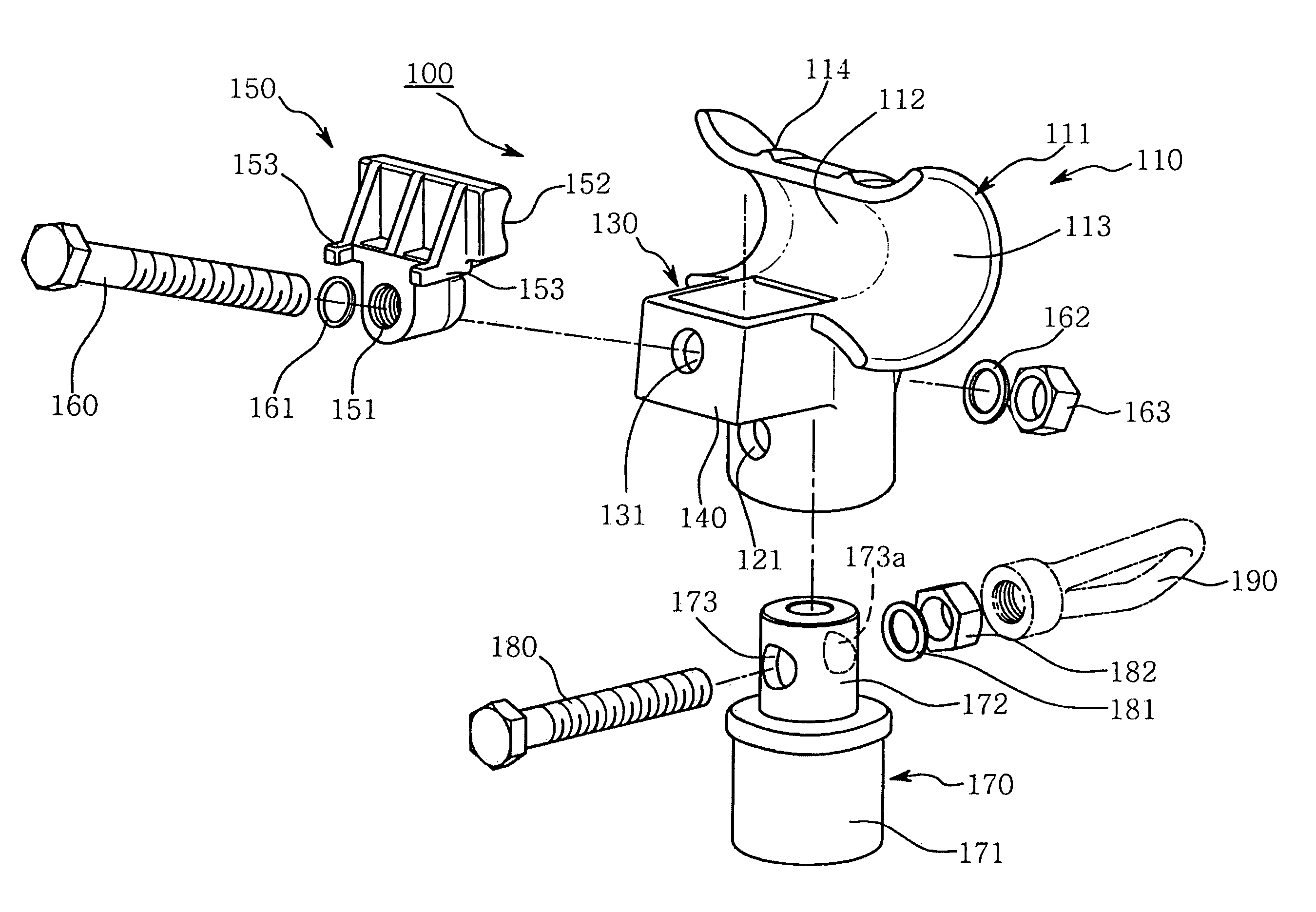
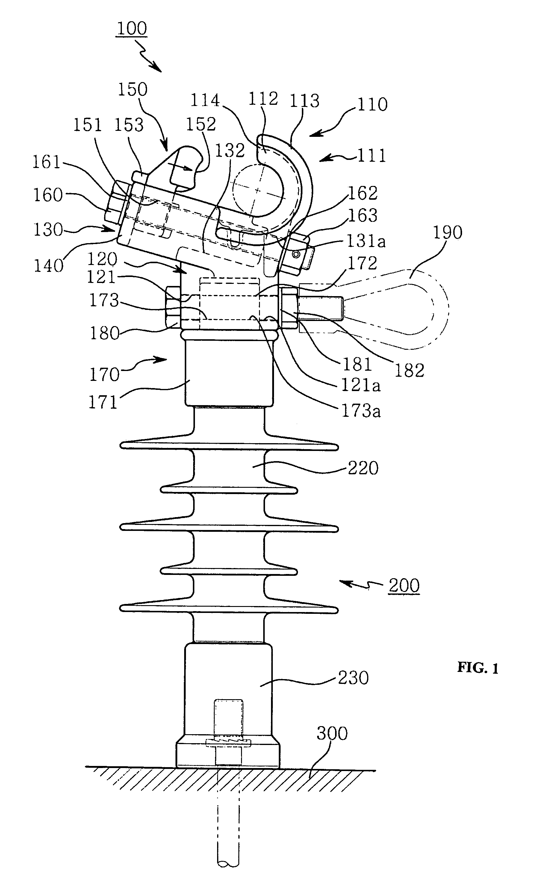
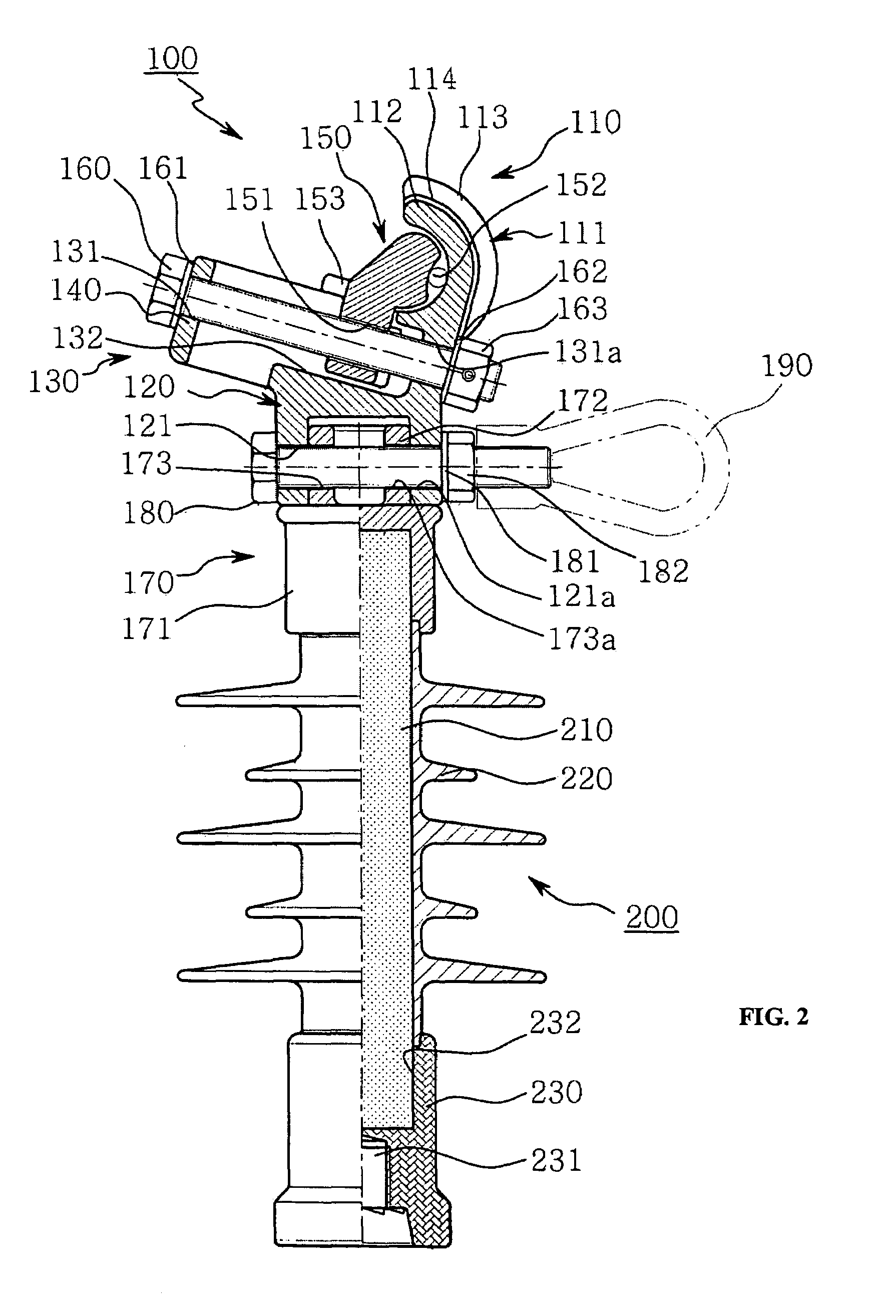
[0034]As shown in FIGS. 1 to 5, an electrical power line insulator has an end clamp 100 fastened to the upper end of an insulator housing 200 using a bolt 180 and a nut 182, so that it is possible to easily separate the end clamp 100 and the insulator housing 200 from each other.

[0035]The insulator housing 200 includes a post 210 in the form of an FRP rod. The post 210 is coupled to the insulator housing 200 by insert forming using insulating rubber 220. The post 210 is inserted into the insulator housing 200 such that both sides of the post, that is to say the upper and lower portions of the post 210, protrude therefrom by a predetermined distance. An upper fitting part 170 and a lower base fitting part 230 are assembled with the upper and lower portions of the post 210.

[0036]The post 210, the insulating rubber 220, and the base fitting part 230 of the insulator housing 200 are equivalent to those of a conventional insulator housing. The insulating rubber 220 may have a plurality o...


PUM

PropertyMeasurementUnit
distanceaaaaaaaaaa
shapeaaaaaaaaaa
electricalaaaaaaaaaa

Abstract

An electrical power line insulator has an end clamp with a saddle for supporting an electrical wire, a track provided on a front surface of the saddle, a keeper for compressing and supporting an electrical wire seated in the saddle, a bolt and a nut for fastening the keeper to the saddle and operable to horizontally move the keeper along the track, and an insulator housing secured to the end clamp and mounted on a support structure. The end clamp and the insulator housing are detachably assembled with each other by means of a cylindrical clamp base integrally provided on a lower portion of the saddle and the track of the clamp and an upper fitting part. The upper fitting part has an assembly cylinder provided on an upper portion of the fitting part to be connected to the cylindrical clamp base, a compression cylinder provided on a lower portion of the fitting part and pressed against a post of the insulator housing, and a bolt and a nut fastening the cylindrical clamp base of the clamp to the assembly cylinder of the upper fitting part.

Description

FIELD OF INVENTION[0001]The present invention relates to electrical power line insulators.BACKGROUND OF THE INVENTION[0002]An electrical power line insulator having an end clamp is usually used to support an electrical wire of a distribution line. After the electrical wire is seated in a saddle, a keeper is moved in a track to tightly engage and support the outer portion of the electrical wire.[0003]Electrical power line insulators having such end clamps have been developed using various technologies over several decades. Recently, in order to enhance the safety and convenience of installation, technologies improved in various ways have been suggested.[0004]Electrical power line insulators are classified either as separated-type or integrated-type. A separated-type electrical power line insulator is constructed so that an end clamp for supporting an electrical power line and an insulator housing mounted on a support structure, such as a cross arm of an electric pole, are manufacture...

Claims


Application Information

Patent Timeline
Patent Type & Authority Patents(United States)
IPC IPC(8): H01B17/00
CPCH01B17/16Y10T24/44598
Inventor KIM, BONG JOO
Owner KIM BONG JOO
Why Eureka
Try Eureka