Rotational retaining mechanism for storage device

a storage device and rotating technology, applied in the direction of electrical apparatus casings/cabinets/drawers, furniture parts, instruments, etc., can solve the problems of difficult to assemble the storage device back in place, easy loss of screws after disassembly, time-consuming disassembly process, etc., to increase the efficiency of maintenance and assembly, and expand the operating space

Active Publication Date: 2008-10-07
LITE ON TECH CORP
View PDF7 Cites 25 Cited by
  • Summary
  • Abstract
  • Description
  • Claims
  • Application Information

AI Technical Summary

Benefits of technology

[0006]The present invention provides a rotational retaining mechanism for storage devices, which has a movable and rotatable retaining mechanism for enlarging the operating space during maintenance and assembly that enables the storage devices to be unlocked quickly from a locked condition for raising the efficiency of maintenance and assembly.
[0007]In addition, the rotational retaining mechanism for storage devices of the prevent invention further provides a safeguarding design to prevent dangerous operations taking place after the storage devices have been unlocked.

Problems solved by technology

The dismounting processes for the above-mentioned storage devices are time-consuming and the screws are easily lost after dismounting.
Sometimes it is even difficult to assemble the storage devices back in place.
Therefore, the retaining mechanism for storage devices of the prior art is still somewhat inconvenient and can be improved upon.

Method used


Image

  • Rotational retaining mechanism for storage device
  • Rotational retaining mechanism for storage device
  • Rotational retaining mechanism for storage device

Examples


Embodiment Construction

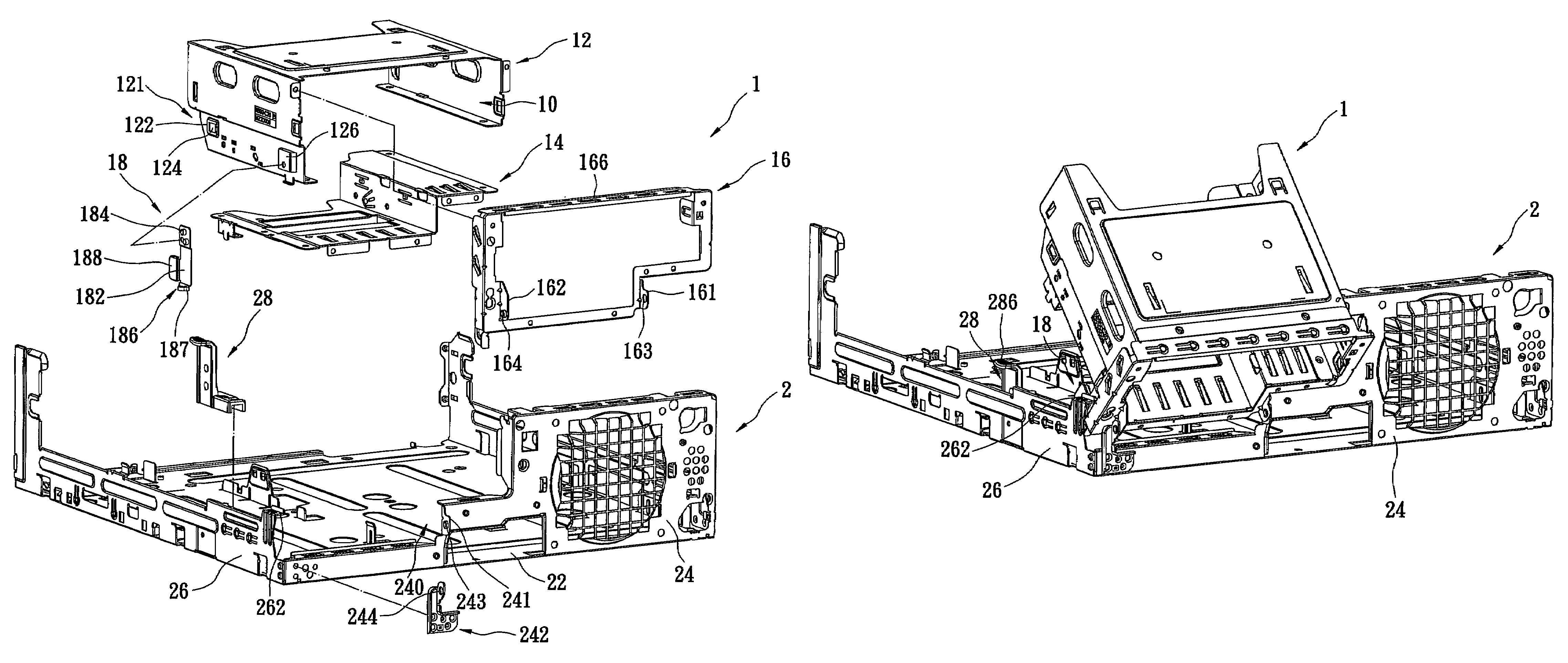
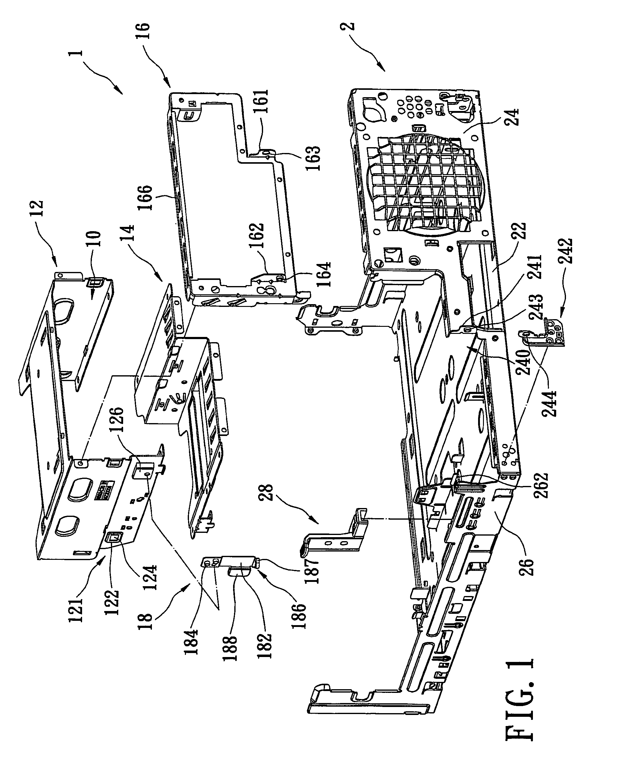
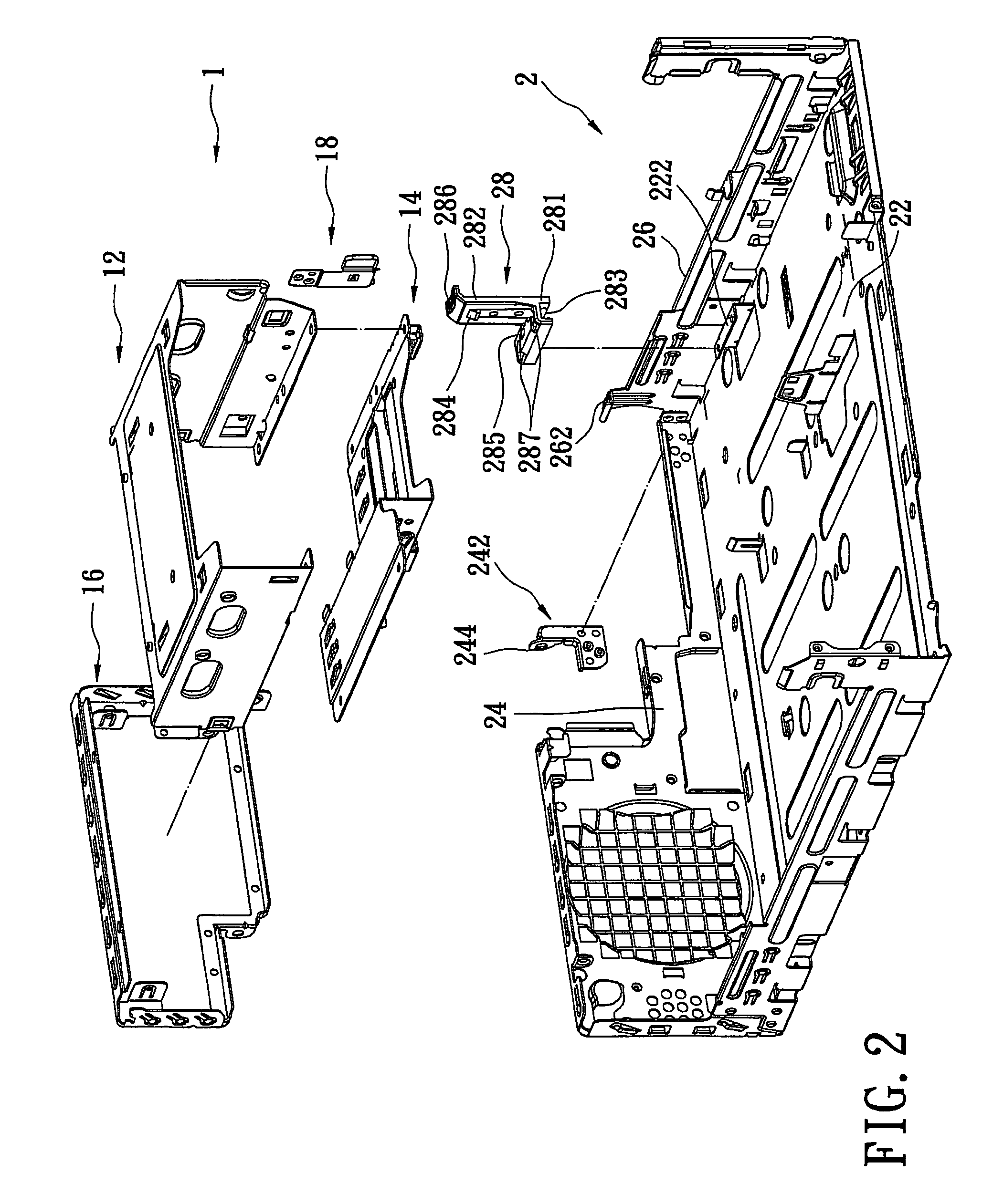
[0022]Reference is made to FIGS. 1 to 4, which are perspective views of a rotational retaining mechanism for storage devices according to the present invention. The present invention provides a rotational retaining mechanism for storage devices, which includes a modular frame 1 for receiving storage devices (not shown), a housing 2 for receiving the modular frame 1, and a retaining buckle 28 for fixing the modular frame 1 in the housing 2. The housing 2 can be a part of computer host casing. The present invention is especially adapted to a miniature casing, wherein the modular frame 1 is rotatably mounted in the housing 2 so that the operating space for maintenance and assembly is enlarged for the user.

[0023]The housing 2 has a bottom board 22, a stopping part 262 protruded upwardly from the bottom board 22, and a front board 24 protruded from a front edge of the bottom board 22. In this embodiment, the housing 2 further includes a side board 26 protruded from one side of the bottom...


PUM


Abstract

A rotational retaining mechanism for storage devices allows storage devices to be unlocked quickly in a rotatable way thereby enlarging the operating space in a housing. The rotational retaining mechanism includes a housing, a modular frame for receiving storage devices and a retaining buckle. The housing has a bottom board, a stopping part protruded upwardly from the bottom board, and a front board. The front board has a receiving entry and a pair of pivotal parts respectively formed at two sides thereof. The module frame has a pair of pivotal parts for mounting pivotally with the pivotal parts of the housing, a holding tab, and a clipping part. The holding tab is held by the stopping part of the housing, when the module frame is opened. The retaining buckle is positioned on the housing and clipped with the clipping part when the modular frame is closed.

Description

BACKGROUND OF THE INVENTION[0001]1. Field of the Invention[0002]The present invention relates to a rotational retaining mechanism for storage devices, and more particularly, to a retaining mechanism for fixing a storage device (such as a CD-ROM drive, a HD (hard disk) drive, or a card reader) in a rotatable and movable way in a host housing.[0003]2. Description of the Prior Art[0004]Storage devices in a conventional computer casing, such as a CD-ROM drive, a HD drive, a FD (floppy disk) drive or a card reader, are almost always fixed in frames of the host casing and are not movable. Sometimes there is a need to dismount the storage devices from the host casing to get more operating space during assembly or maintenance of the computer. The dismounting processes for the above-mentioned storage devices are time-consuming and the screws are easily lost after dismounting. Sometimes it is even difficult to assemble the storage devices back in place.[0005]Therefore, the retaining mechanism...

Claims


Application Information

Patent Timeline
Patent Type & Authority Patents(United States)
IPC IPC(8): H05K5/00A47B81/00A47B97/00H05K7/00H05K7/16
CPCG06F1/187
Inventor HUANG, YA-CHI
Owner LITE ON TECH CORP
Why Eureka
Try Eureka