Heat fixing device capable of preventing deterioration of a temperature sensor and an image forming apparatus

a technology of temperature sensor and fixing device, which is applied in the direction of optical radiation measurement, instruments, and sensing radiation from moving bodies, etc., can solve the problems of deteriorating sensing accuracy, peeling of toner adhering to the temperature sensor, and difficulty in disposing of infrared sensors in the vicinity of heating rollers that are maintained at a high heat fixing temperatur

Inactive Publication Date: 2008-10-07
BROTHER KOGYO KK
View PDF41 Cites 6 Cited by
  • Summary
  • Abstract
  • Description
  • Claims
  • Application Information

AI Technical Summary

Benefits of technology

[0014]The present invention has been devised in the light of the above problems. An object of the present invention is to provide a heat fixing device and an image forming apparatus provided therewith that achieves accurate temperature sensing while maintaining the distance between the heating member and the temperature sensing means, preventing attenuation of infrared rays radiating from the heating member and improving the durability of the temperature sensor.

Problems solved by technology

The contact type of temperature sensor, however, may raise problems in that the sensing accuracy thereof may deteriorate if toner adheres to the temperature sensor, and that the toner adhering to the temperature sensor may peel off to damage the heating roller or fall onto the paper to dirty it.
However, since an infrared sensor generally has a low thermal resistance, it is difficult to dispose the infrared sensor in the vicinity of a heating roller that is maintained at a high heat fixing temperature.
If the spacing is too far, the infrared sensor will sense the temperature of portions other than the surface of the heating roller, which may lead to errors in the sensing of the surface temperature of the heating roller.
This is inconvenient in that the radiation intensity of infrared rays sensed by the infrared sensor is not so sufficient as to achieve accurate temperature sensing.
In such a case, since the non-contact type of temperature sensor usually has a lower thermal resistance, the usage of the non-contact type of temperature sensor may raise problems in that the temperature sensing accuracy may fall and the non-contact type of temperature sensor may deteriorate.
Furthermore, if the attachment position of the non-contact type of temperature sensor with respect to the heating roller is displaced, the quantity of infrared rays arriving at the non-contact type of temperature sensor will change, raising a problem in that the temperature sensing accuracy will fall.

Method used


Image

  • Heat fixing device capable of preventing deterioration of a temperature sensor and an image forming apparatus
  • Heat fixing device capable of preventing deterioration of a temperature sensor and an image forming apparatus
  • Heat fixing device capable of preventing deterioration of a temperature sensor and an image forming apparatus

Examples


embodiment 1

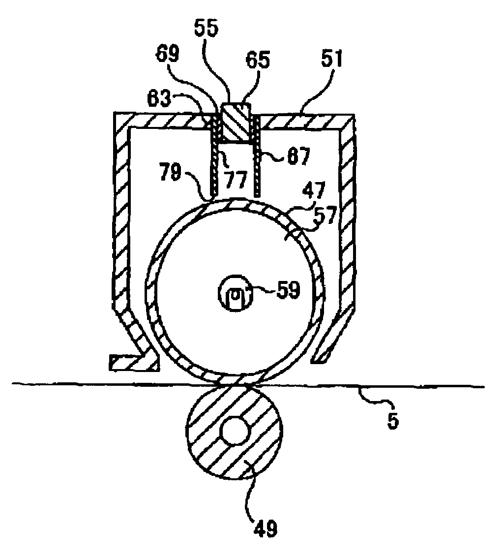
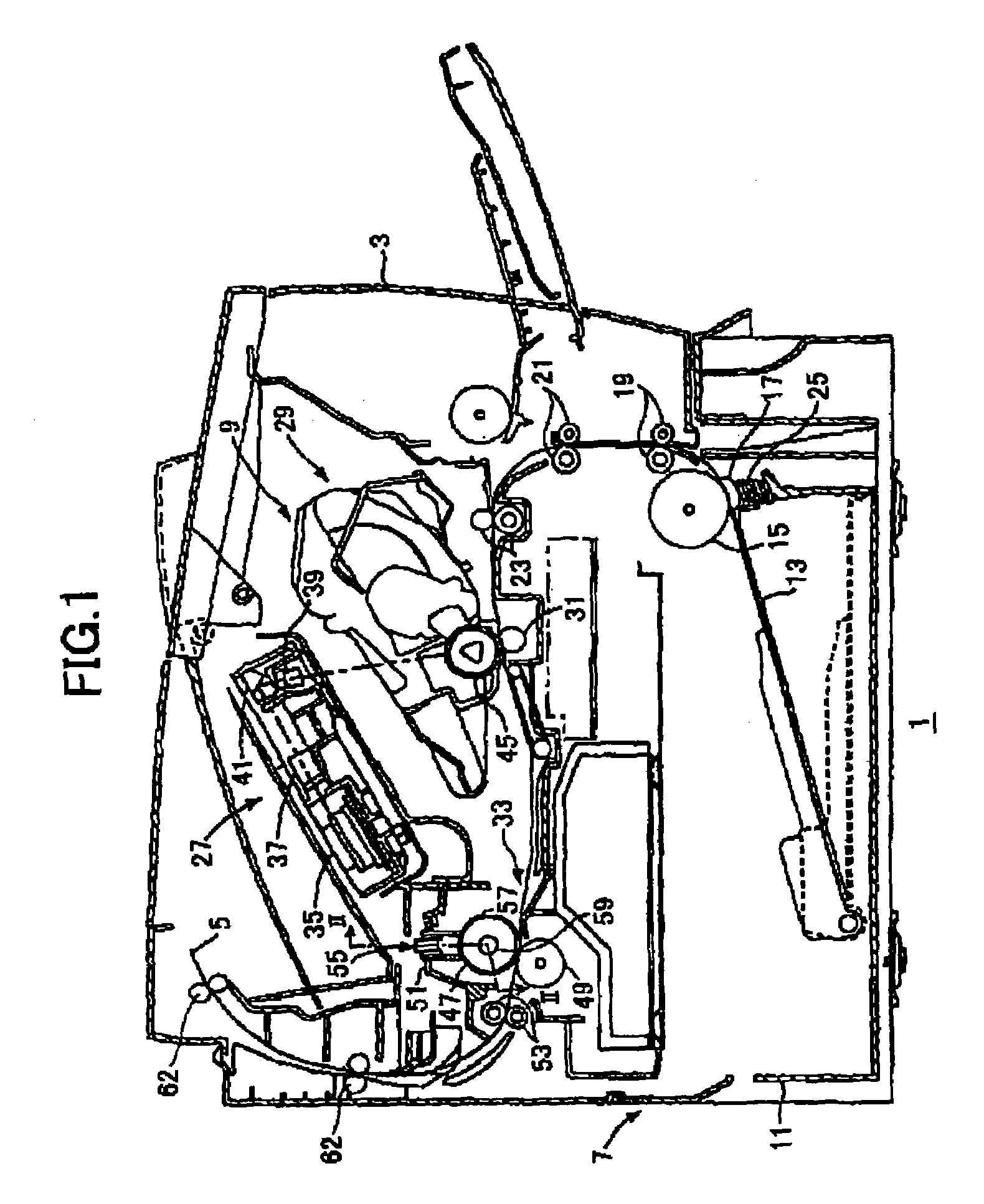
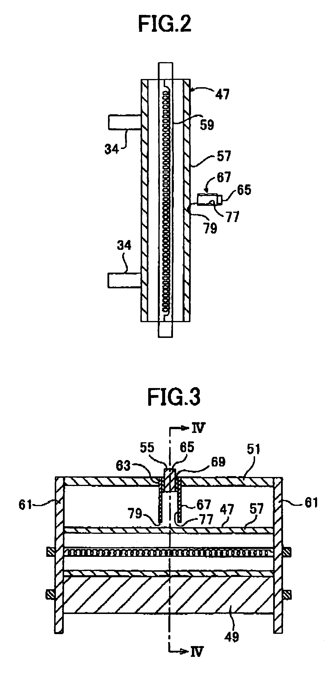
[0139]a) The description is first made for explaining the configuration of a laser printer in accordance with the Embodiment 1, with reference to FIG. 1. Note that FIG. 1 shows a section through the side of essential components of the laser printer. A section taken along the jointed line II-II in FIG. 1 is shown in FIG. 2, to illustrate the positional relationship between a heating roller 47, a temperature sensor 65, and removal claws 34.

[0140]A laser printer 1 includes a feeder portion 7 for supplying paper 5 as a fixing medium and an image forming portion 9 for forming a predetermined image on the supplied paper 5 in a main casing 3.

[0141]The feeder portion 7 has a paper supply tray 11 installed in a removable manner; a paper press plate 13 provided within the paper supply tray 11; a paper-supply roller 15 and a paper-supply pad 17 provided above one end of the paper supply tray 11; feed rollers 19 and 21 provided on the downstream side of the paper-supply roller 15 along the pape...

embodiment 2

a) The configuration of the laser printer 1 of the Embodiment 2 will now be described with reference to FIGS. 8 and 9.

[0194]FIG. 8 is a section as seen from the front side (the right-hand side in FIG. 1) of the temperature measurement unit 55 and peripheral portions thereof and FIG. 9 is a section taken along the line IX-IX of FIG. 8.

[0195]Note that the configuration of the laser printer 1 of the Embodiment 2 is basically the same as that of the laser printer 1 of the Embodiment 1, so that a description of similar portions is omitted.

[0196]In the Embodiment 2, a pair of roller support members 61 that support the axes of the heating roller 47 and the press roller 49 at the left and right sides are connected by a conduit support member 87 that is a plate-shaped member that is disposed horizontally. The conduit 67 is fitted into a conduit attachment hole 89 provided at the center of the conduit support member 87.

[0197]The temperature sensor 65 is attached to the temperature measurement...

embodiment 3

[0203]The description now turns to a laser printer according to Embodiment 3.

[0204]a) The configuration of the laser printer 1 of the Embodiment 3 will be described first, with reference to FIGS. 10 and 11. This FIG. 10 is a section as seen from the front side (the right-hand side in FIG. 1) of the temperature measurement unit 55 and peripheral portions thereof, and FIG. 11 is a section taken along the line XI-XI of FIG. 10.

[0205]Note that the configuration of the laser printer 1 of the Embodiment 3 is basically the same as that of the laser printer 1 of the Embodiment 2. Thus portions that are the same as the corresponding ones of Embodiment 2 are omitted herein.

[0206]In the laser printer 1 in accordance with the Embodiment 3, there is no thermal insulation member 69 between the temperature sensor 65 and the conduit 67 in the temperature measurement unit 55, so that the corresponding area to the thermal insulation member 69 is a gap 91. In other words, the temperature sensor 65 and...


PUM


Abstract

A heat fixing device capable of preventing deterioration of a temperature sensor by measuring the surface temperature of a heating roller at all times, and an image forming apparatus. The heat fixing device includes a temperature measurement unit for measuring the surface temperature of the heating roller. The temperature measurement unit further includes the temperature sensor, a conduit having a reflective surface formed inside thereof to lead infrared rays radiating from the heating roller to the temperature sensor, and a thermal insulation member installed between the conduit and the temperature sensor.

Description

CROSS-REFERENCE RELATED APPLICATION[0001]This application is a continuation-in-part application of PCT / JP02 / 11845 of an international application designating the United States of America filed on Nov. 13, 2002 (international filing date).BACKGROUND OF THE INVENTION[0002]1. Field of the Invention[0003]The present invention relates to a heat fixing device and an image forming apparatus provided with the heat fixing device.[0004]2. Description of Related Art[0005]An image forming apparatus such as a laser printer is usually provided with a heat fixing device having a heating roller and a press roller for heating and fixing a toner image that has been transferred onto paper. In the heat fixing device, the toner image transferred onto the paper is heated and fixed as the paper passes between the heating roller and the press roller.[0006]The heating roller of such a heat fixing device usually has a heater such as a halogen lamp incorporated therein and a temperature sensor provided for se...

Claims


Application Information

Patent Timeline
Patent Type & Authority Patents(United States)
IPC IPC(8): G03G15/20G01J5/00G01J5/08
CPCG01J5/0022G01J5/08G01J5/0809G03G15/2039G01J5/0893G03G15/2003G03G15/2014G01J5/0815G01J5/0808
Inventor SUZUKI, MASASHIHATTORI, TOMOAKI
Owner BROTHER KOGYO KK
Why Eureka
Try Eureka