Fiber optic paintball marker

a paintball marker and fiber optic technology, applied in the field of paintball markers, can solve the problems of affecting the look and design of the marker, the detector to the harsh environment of the paintball marker, and the forward weight shift of the marker, so as to improve the effect of environmental effects, and improve the balance of the marker

Inactive Publication Date: 2008-10-14
KEE ACTION SPORTS I
View PDF85 Cites 10 Cited by
  • Summary
  • Abstract
  • Description
  • Claims
  • Application Information

AI Technical Summary

Benefits of technology

[0013]Objects of the present invention include isolation of the electric circuit from the marker; removing optical sensors from the harsh paintball environment and encasing them in a protective area such as the body of the marker or a hollow trigger handle; monitoring areas that are difficult to reach with bulky sensors by utilizing fiber optic transmition capabilities to remotely position the sensors, improving the balance of the marker by moving the weight of the sensor to a rearward or neutral position while adding only minimal weight associated with an optical cable; improving the speed of repair of a marker by centralizing the electrical board, and providing quick disconnects for the fiber optic system at either the cable to sensor interface or the sensor to electrical circuit interface.

Problems solved by technology

As noted by the disclosure and the housings shown in FIGS. 1 through 3d of this patent, the placement of the actual sensor at the detecting area results in large bulk and weight placed out on the lever arm of the barrel which gives a forward weight shift to the marker.
This placement also exposes the detector to the harsh environment that paintball markers face during use.
Finally, this placement also interferes with the look and design of the marker.
As noted in the problems associated with the prior art, paintball markers are exposed to extreme and harsh environments both on and off the playing field.
In addition to the normal effects of operating the markers, markers get exposed to water, humidity, high speed impacts from paintballs shot by other players as well as the marker being banged against obstacles, jarring movements during both play with the marker as well as shipment and transportation, and high and low temperatures including those found in shipment containers or the trunks of automobiles during normal weather cycles.
Also, salt corrosion becomes a problem in coastal areas.
The prior art fails to teach designs to overcome these problems.
Thus, it may be seen that these prior art patents are very limited in their teaching and utilization, and an improved marker is needed to overcome these limitations.

Method used


Image

  • Fiber optic paintball marker
  • Fiber optic paintball marker
  • Fiber optic paintball marker

Examples


Embodiment Construction

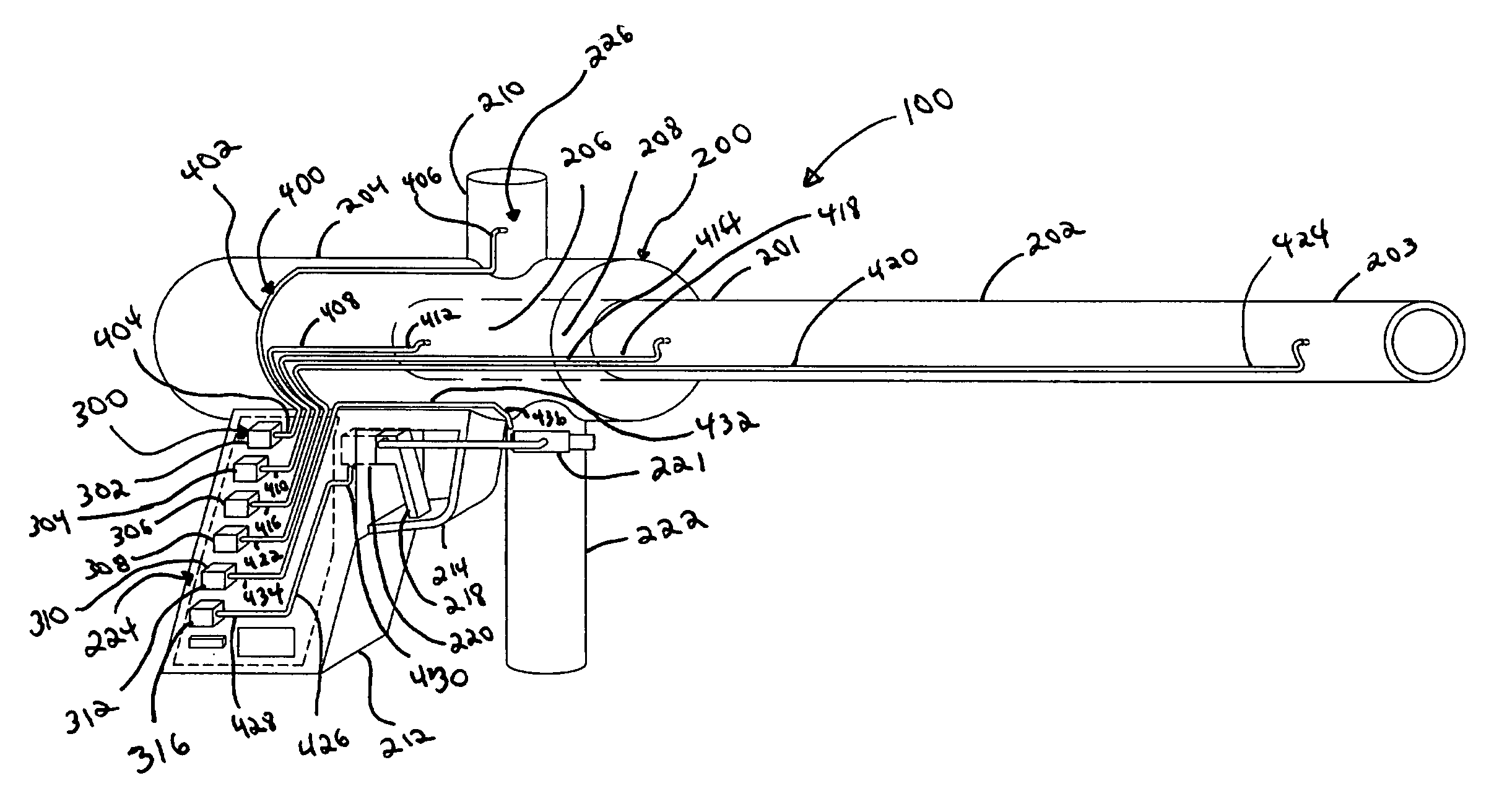
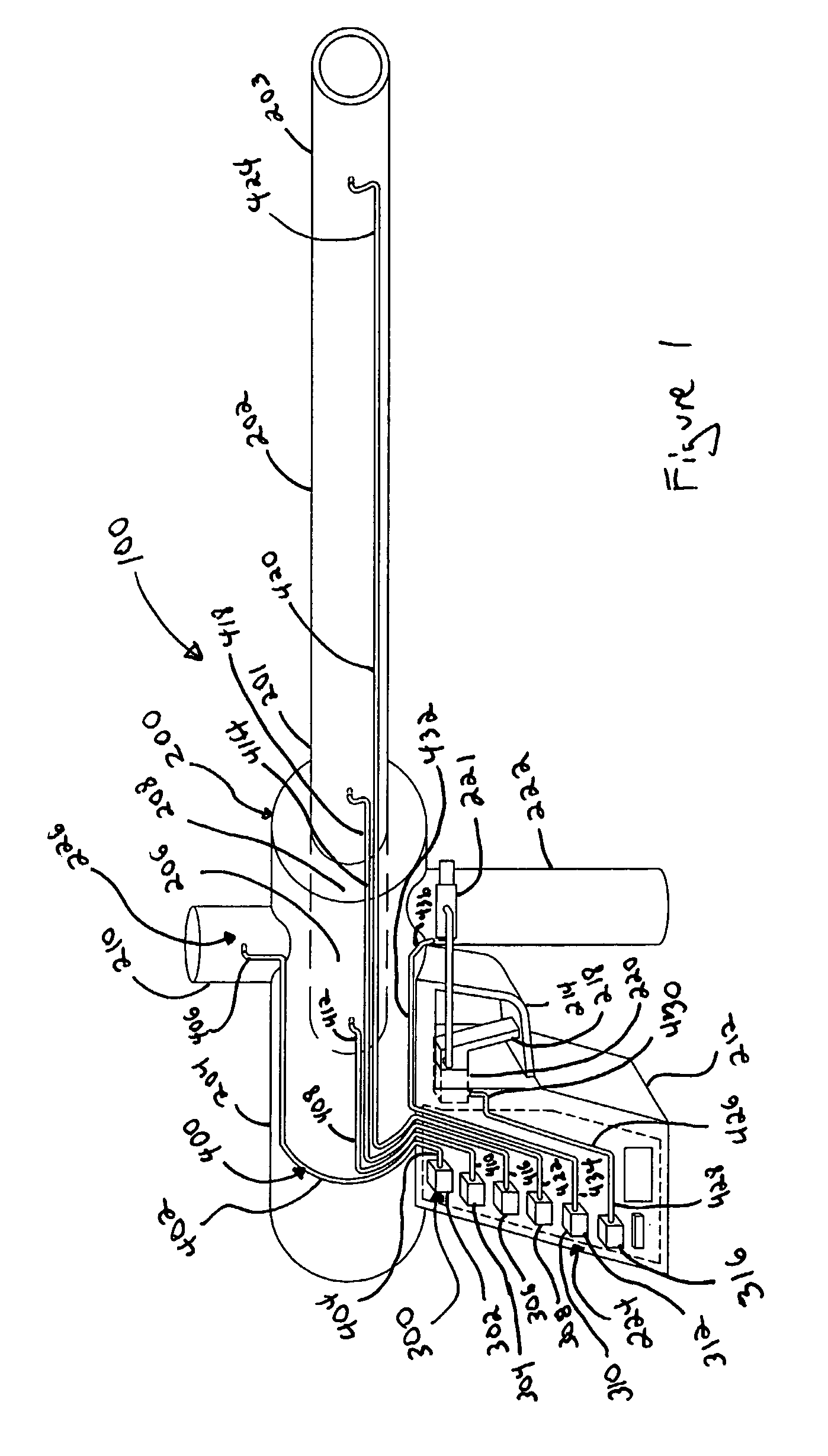
[0018]As shown in FIG. 1 of the drawings, one exemplary embodiment of the present invention is generally shown as a paintball marker 100 having a frame structure 200. The frame structure 200 includes a barrel 202 mounted to the body 204. The barrel 202 includes a body proximal barrel end 201 and a body distal barrel end 203. The body 204 defines a projectile loading area 206 and a breech 208 aligned with the bore of the barrel 202. A projectile receiver 210 is mounted to the top of the body 202 and a trigger frame 212 is mounted underneath. The trigger frame includes a main body 213 and a trigger guard 214 protecting a trigger 216 which includes a lever arm 218 mounted to a trigger body 220. A regulator 222 is also mounted to the body 204. For convenience when referring to areas of the body, the attachment location for an optical sensors will generally be referred to as a mounting area 224 and the location which is to be monitored by the optical sensors will generally be referred to...


PUM


Abstract

A paintball marker utilizing fiber optic cables and quick disconnects to create an isolated electrical circuit which is more robust to environmental effects while improving marker balance by relocating the sensor weight. A paintball marker is provided using a frame structure defining a mounting area and a distal sensing area with an optical sensor connected to the frame at the mounting area and a fiber optic cable connected between the optical sensor and the distal sensing area. Both reflective and broken beams sensors are taught for use with the present invention as well as a light source providing light through an optic supply line connected between the light source and the distal sensing area.

Description

CROSS-REFERENCE TO RELATED APPLICATIONS[0001]This application claims priority to and is a continuation-in-part of provisional application Ser. No. 60 / 606,064, filed Aug. 31, 2004.STATEMENT REGARDING FEDERALLY SPONSORED RESEARCH OR DEVELOPMENT[0002]Not Applicable.REFERENCE TO A MICROFICHE APPENDIX[0003]Not Applicable.RESERVATION OF RIGHTS[0004]A portion of the disclosure of this patent document contains material which is subject to intellectual property rights such as but not limited to copyright, trademark, and / or trade dress protection. The owner has no objection to the facsimile reproduction by anyone of the patent document or the patent disclosure as it appears in the Patent and Trademark Office patent files or records but otherwise reserves all rights whatsoever.BACKGROUND OF THE INVENTION[0005]1. Field of the Invention[0006]The present invention relates to the field of paintball markers for launching paintballs as projectiles. In particular, the present invention relates specif...

Claims


Application Information

Patent Timeline
Patent Type & Authority Patents(United States)
IPC IPC(8): F41B11/00
CPCF41B11/57F41B11/71
Inventor ORR, JEFFREY GEORGE
Owner KEE ACTION SPORTS I
Why Eureka
Try Eureka