Method to detect termite infestation in a structure

a technology of non-destructive detection and structure, applied in the direction of material flaw investigation, optical radiation measurement, instruments, etc., can solve the problems of difficult to put a dollar amount estimate on termite damage, house is very susceptible to termite attack, and the infestation is extremely destructive to wood materials, etc., to achieve less specific or accurate detection, efficient screening, and large area

Inactive Publication Date: 2008-10-14
UNIVERSITY OF MISSISSIPPI
View PDF43 Cites 4 Cited by
  • Summary
  • Abstract
  • Description
  • Claims
  • Application Information

AI Technical Summary

Benefits of technology

[0008]Another method often used to detect termites is to tap the surface of the wood while listening for a characteristic sound indicative of an underlying gallery void. When a suspected area is located, the inspector applies a sharp probe, such as a screwdriver, to break the wood surface and locate wood galleries and live termites. This method has significant disadvantages. The confirmation of an active infestation requires some localized damage to the wood. Also, when termites are exposed in this manner, the destruction induces termites to retreat from the disturbed area and may reduce the effectiveness of a subsequent localized treatment.
[0011]Detection devices that rely on sensing the presence of termite-created gases eliminate the need to use bait to attract the termites, and, in theory, they can signal the actual locations of the termites. A significant disadvantage, however, is that the gases must be abstracted within a confined space, such as within the walls of a structure. These devices are thus unsuitable for detecting termites in wood that is not within a confined space. Moreover, the use of these devices to detect termites is very time-consuming and costly as a result.
[0016]Devices relying on acoustic detection appear to offer the best combination of accuracy and lack of destruction. Such devices, however, generally do not take into account the full range of termite sounds, as explained above. Moreover, the design of prior devices has generally resulted in only highly localized detection ability, thereby necessitating the taking of many samples or data points, and requiring an inordinate amount of time or number of sensors to completely inspect a structure.
[0019]Preliminary infrared detection has the advantage of covering a much larger area than acoustic detection and, although less specific or accurate than acoustic detection, provides efficient screening and a convenient way of scanning the structure for potential infestations in order to guide placement of detectors in order to carry out more specific tests. In this way, inspection time requirements, and, therefore, costs, are greatly reduced. Further, detection accuracy is greatly increased. The combination of infrared and other detection method couples a quicker but low-specificity screening technique for speed with a high-specificity, slower technique for accuracy and is a significant improvement in the art having important commercial applications.

Problems solved by technology

Termites are extremely destructive to wood material.
It is difficult to put a dollar amount estimate on termite damage.
Untreated foundations make the house very susceptible to termite attack.
It is often very difficult and costly to apply effective control measures after a building has become infested with termites.
It is rarely apparent from visual observation that a termite infestation is active and that wood damage is occurring.

Method used


Image

  • Method to detect termite infestation in a structure
  • Method to detect termite infestation in a structure
  • Method to detect termite infestation in a structure

Examples


Embodiment Construction

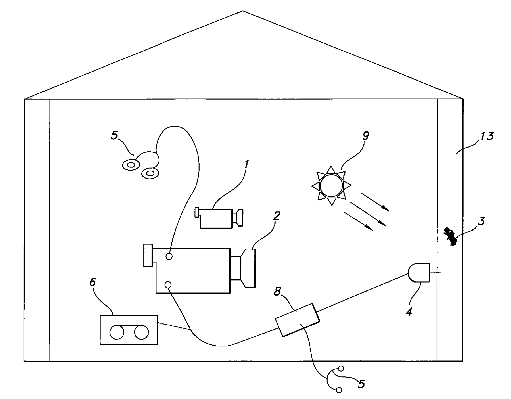
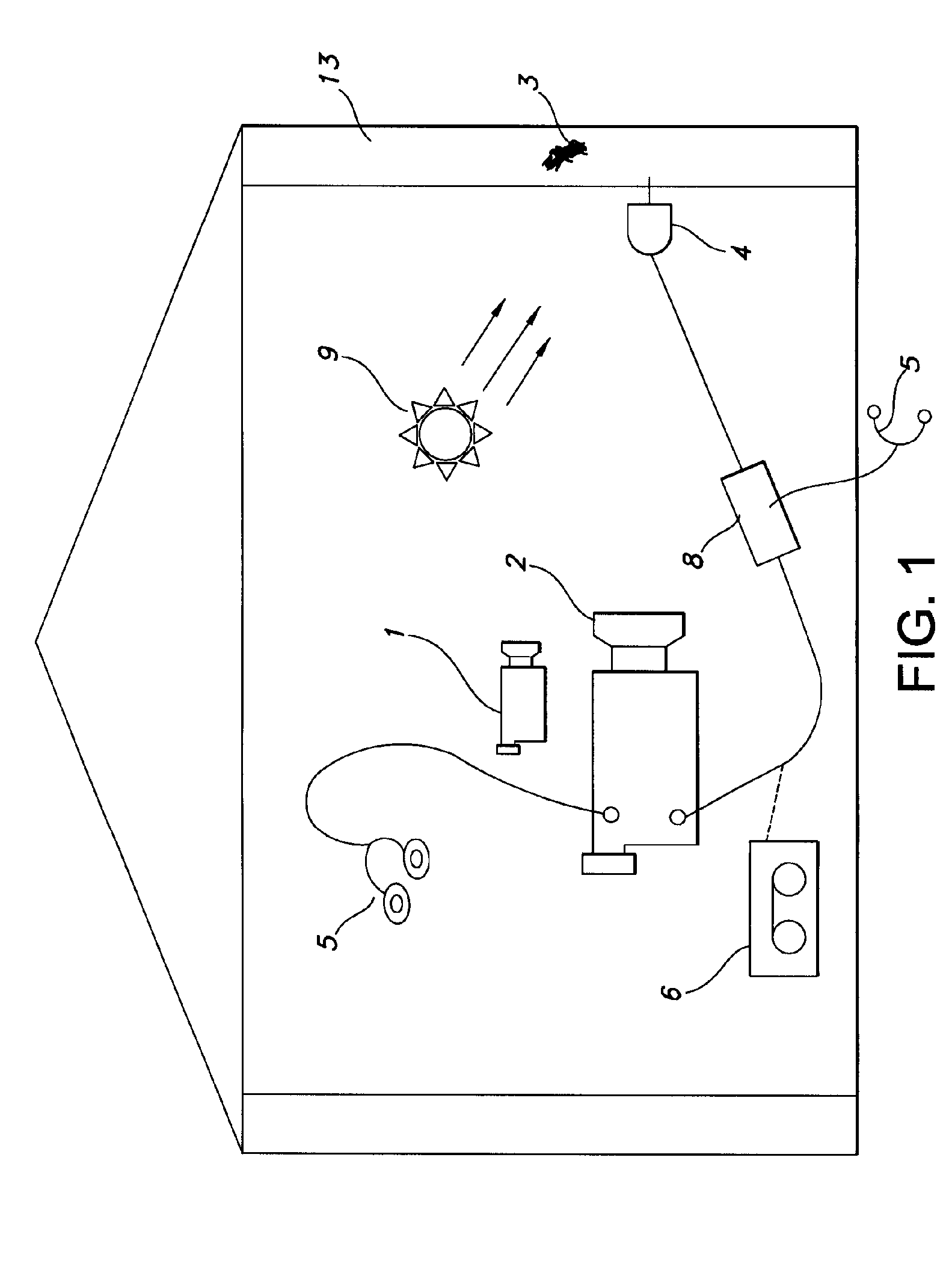
[0028]As schematically depicted in FIG. 1, a preferred embodiment of the apparatus and method of the present invention includes a thermal imaging camera 1 for performing a preliminary scan of a structure 13 in order to locate potential termite infestations sites 3. A thermal imaging camera 1 is used to perform an infrared scan. The structure 13 can be a wooden object, such as a wall stud, paneling or in one embodiment a live tree. Termite infestation sites 3 can be the result of subterranean termite or dry-wood termite activity. In the case of a subterranean termite infestation, the moisture brought in by the subterranean termites will show up as a “suspicious cold or hot spot” in a thermal imaging scan. In the case of a dry-wood termite infestation, a heat or cold source 9 is needed to increase or decrease the temperature of a targeted structure 13. This heat source 9 can be an electric, gas or oil heat source as well as an incandescent or infrared light source. The areas in the ta...


PUM

PropertyMeasurementUnit
frequenciesaaaaaaaaaa
thermal imaging cameraaaaaaaaaaa

Abstract

A method for confirming the presence of termites in a structure, involving a preliminary infrared scan of a structure and confirmation of termite infestation with at least one detector in order to quickly locate potential areas of termite infestation.

Description

CROSS REFERENCE TO RELATED APPLICATIONS[0001]This application is a continuation-in-part and claims the benefit under 35 U.S.C. § 120 of U.S. application Ser. No. 10 / 680,377 filed Oct. 7, 2003 and U.S. application Ser. No. 10 / 708,571 filed Mar. 11, 2004, and 35 U.S.C. § 119(e) of U.S. Provisional Application Ser. No. 60 / 417,257 filed Oct. 9, 2002, hereby specifically incorporated by reference in their entirety.STATEMENT REGARDING FEDERALLY SPONSORED RESEARCH OR DEVELOPMENT[0002]U.S. Department of Agriculture Award # 58-6402-04-040BACKGROUND OF THE INVENTION[0003]This invention relates to nondestructive detection of termite infestation in a structure and, more particularly, to methods for detecting and preventing termite damage.SUMMARY OF THE INVENTION[0004]Termites are extremely destructive to wood material. Termites attack and destroy wood almost everywhere in the world, with the exception of climate zones that experience hard freezing. There are close to fifty species of termites i...

Claims


Application Information

Patent Timeline
Patent Type & Authority Patents(United States)
IPC IPC(8): G01N25/00G01J5/00G01N25/72
CPCA01M1/026A01M1/24G01N25/72A01M2200/011G01N33/46
Inventor LEE, PENG
Owner UNIVERSITY OF MISSISSIPPI
Why Eureka
Try Eureka