Gas separation apparatus, a front wall and a separation rotor thereof

Active Publication Date: 2008-10-14
SULZER MANAGEMENT AG
View PDF13 Cites 11 Cited by
  • Summary
  • Abstract
  • Description
  • Claims
  • Application Information

AI Technical Summary

Benefits of technology

[0011]The present invention aims at eliminating at least some of the problems and disadvantages of the prior art gas separators and gas se

Problems solved by technology

The structure is, however, complicated and expensive to carry out.
A disadvantage relating to the dynamic sealing in view of the present problem, i.e. gas separation, is that it can be used neither with a gas-removing centrifugal pump nor with any other gas-separating rotary apparatus or apparatuses, because there is/are no opening(s) in the expeller disc of a conve

Method used


Image

  • Gas separation apparatus, a front wall and a separation rotor thereof
  • Gas separation apparatus, a front wall and a separation rotor thereof
  • Gas separation apparatus, a front wall and a separation rotor thereof

Examples


Example

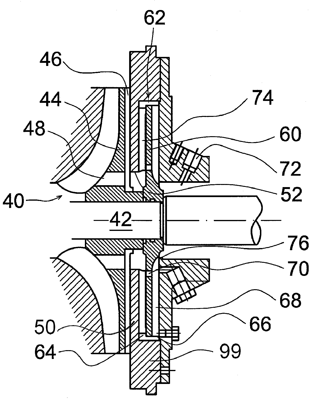
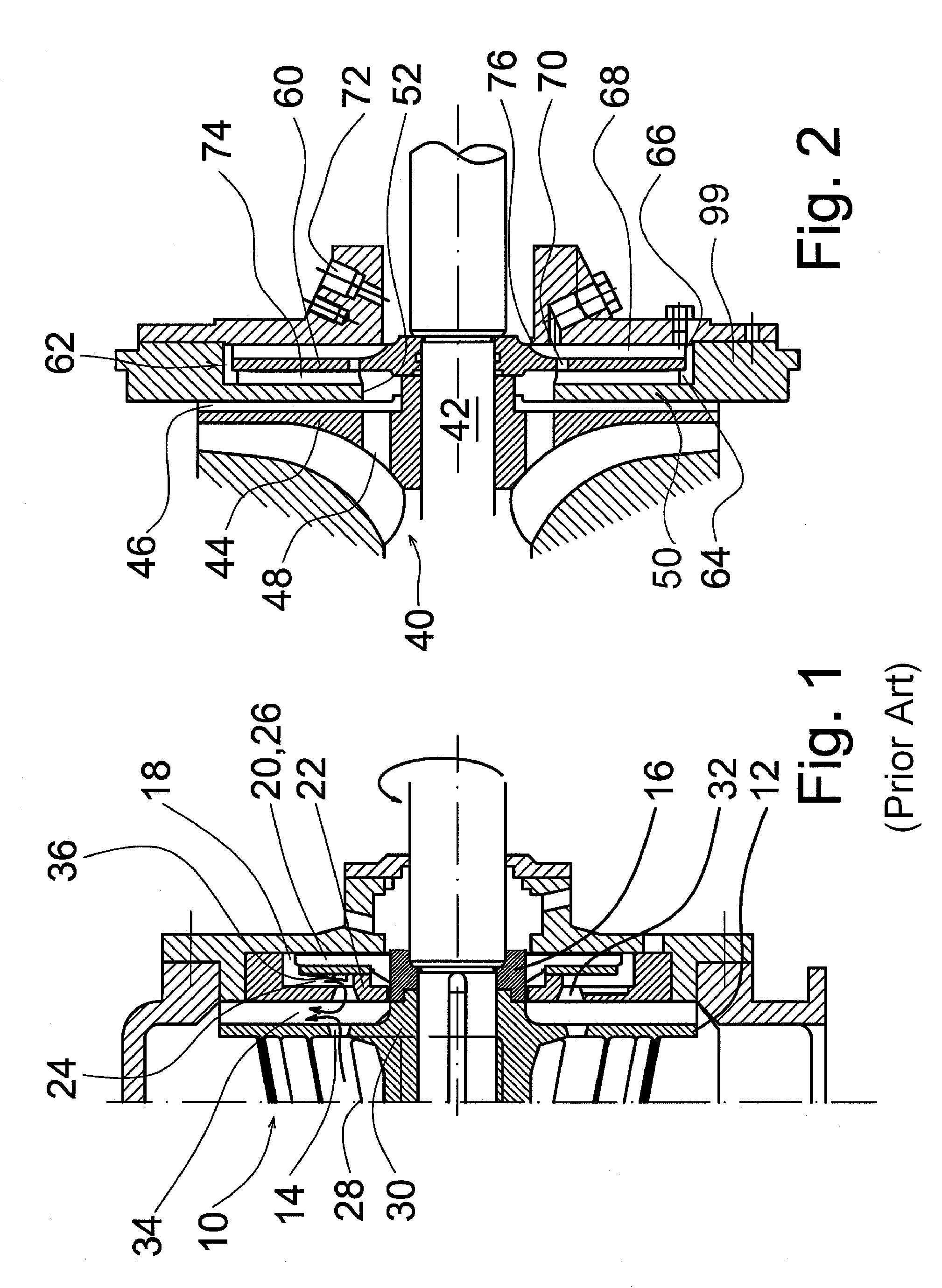
[0020]FIG. 2 illustrates a gas separation apparatus in accordance with a preferred embodiment of the present invention, the separation apparatus being shown in an exemplary manner in connection with a centrifugal pump. In the figure, reference number 40 refers to an impeller of a centrifugal pump, which pumps, from the left along a suction duct (not shown), liquid entering the pump in a conventional manner to a pressure opening (not shown) of the volute of the pump. The impeller is attached to a shaft 42 of the pump, which shaft is mounted at the right with bearings to the bearing housing of the pump already cut away. The impeller 40 consists of working vanes on the front surface of the back plate 44 thereof and so-called rear vanes 46 on the rear surface of the back plate, which rear vanes contribute to preventing the flow of the liquid to be pumped from entering the other side of the so-called rear wall 50 of the pump. The rear vanes 46 may extend radially to the shaft 42 of the p...


PUM

PropertyMeasurementUnit
Timeaaaaaaaaaa
Pressureaaaaaaaaaa
Diameteraaaaaaaaaa

Abstract

The present invention relates to a gas separation apparatus, a front wall and a separation rotor thereof. The invention especially relates to the modification of the separation rotor and/or the front wall of the gas separation apparatus in such a way that liquid or liquid suspension separated from a mixture containing gas and liquid or liquid suspension by means of said separation rotor may be recirculated as simply as possible back to the process flow at the same time as the gas separated from said liquid or liquid suspension is guided out of the process.
A characteristic feature of the gas separation apparatus comprising a front wall (50) and a separation chamber (62) arranged in communication with said front wall (50), a disc (60) mounted on the shaft (42) and located within said separation chamber, said disc dividing the separation chamber (62) to a so called front chamber (64), and a so called rear chamber (66), vanes (68) arranged to said disc (60), and at least one opening (70) for allowing gas-containing liquid or gas to enter the rear chamber (66) on the rear side of the disc (60), is that the front wall (50) surface facing the front chamber (64) is at least partially provided with ribs (74), by means of which the rotation of the liquid in the separation chamber (62) is prevented in the front chamber (64).

Description

CROSS-REFERENCE TO RELATED APPLICATIONS[0001]This application claims the priority of Finnish Application No. 20050674 filed on Jun. 22, 2005, and Finnish Application No. 20050733 filed on Jul. 8, 2005, the disclosures of which are incorporated herein by reference.BACKGROUND OF THE INVENTION[0002]The present invention relates to a gas separation apparatus, a front wall and a separation rotor thereof. The present invention especially relates to the modification of the separation rotor and / or the front wall of the gas separation apparatus in such a way that the liquid or liquid suspension separated by the separation rotor from a mixture containing gas and liquid or gas and liquid suspension may be recirculated as simply as possible back to a process flow as the gas separated from the liquid or liquid suspension is guided out of the process. The present invention may be applied in all such positions that gas separates from a process liquid flow to a certain spot in the flow, wherefrom t...

Claims


Application Information

Patent Timeline
IPC IPC(8): B01D45/14B01D19/00F04BF04D9/00
CPCB01D19/0052F04D9/003F04D7/04
Inventor RAUSSI, PEKKAKOIVIKKO, MATTI
Owner SULZER MANAGEMENT AG
Why Eureka
Try Eureka