
Parallel-plate diffusion gas dehumidifier and methods for use

a gas dehumidifier and parallel plate technology, applied in the field of gas samplers, can solve the problems of airborne particulates, either occurring, hazardous to human health, water vapor in the sampled gas stream can interfere with the accurate measurement, etc., and achieve the effect of minimizing the development of the boundary layer

Active Publication Date: 2008-10-14
THERMO ELECTRON A DE
View PDF28 Cites 18 Cited by
  • Summary
  • Abstract
  • Description
  • Claims
  • Application Information

AI Technical Summary

Benefits of technology

[0011]A still further aspect of the invention is a membrane support structure adapted to provide at least one flow passage for transmitting a treatment fluid past the membrane, the support structure including a plate having a surface; and a plurality of ribs mounted to the plate, the plurality of ribs adapted to support the membrane; wherein when the membrane is mounted to the support structure, the membrane, the plurality of ribs, and the surface of the plate define the boundaries of the at least one flow passage. In one aspect, the at least one flow passage comprises a cross section sized to maximize either treatment fluid flow velocity or treatment fluid flow turbulence for a given treatment fluid flow rate, for example, to minimize the development of a boundary layer on the membrane.

Problems solved by technology

Air borne particulate, either occurring naturally, such as pollen and dust, or generated through industry, such as smoke or automobile exhaust, can be hazardous to human health.
The presence of water vapor in a sampled gas stream can interfere with the accurate measurement of, for example, the mass of particulate matter in the gas stream.
For example, conventional water vapor removal devices, that is, “dehumidifiers” or “dryers” designed to remove water vapor from a gas stream, for example, those disclosed in U.S. Pat. Nos. 6,651,480; 6,151,953; 6,171,374; 5,932,795; 5,571,945; and 3,735,559, may typically interfere with the goal of the particulate sampling system, that is, collecting particles.

Method used


Image

  • Parallel-plate diffusion gas dehumidifier and methods for use
  • Parallel-plate diffusion gas dehumidifier and methods for use
  • Parallel-plate diffusion gas dehumidifier and methods for use

Examples


Embodiment Construction

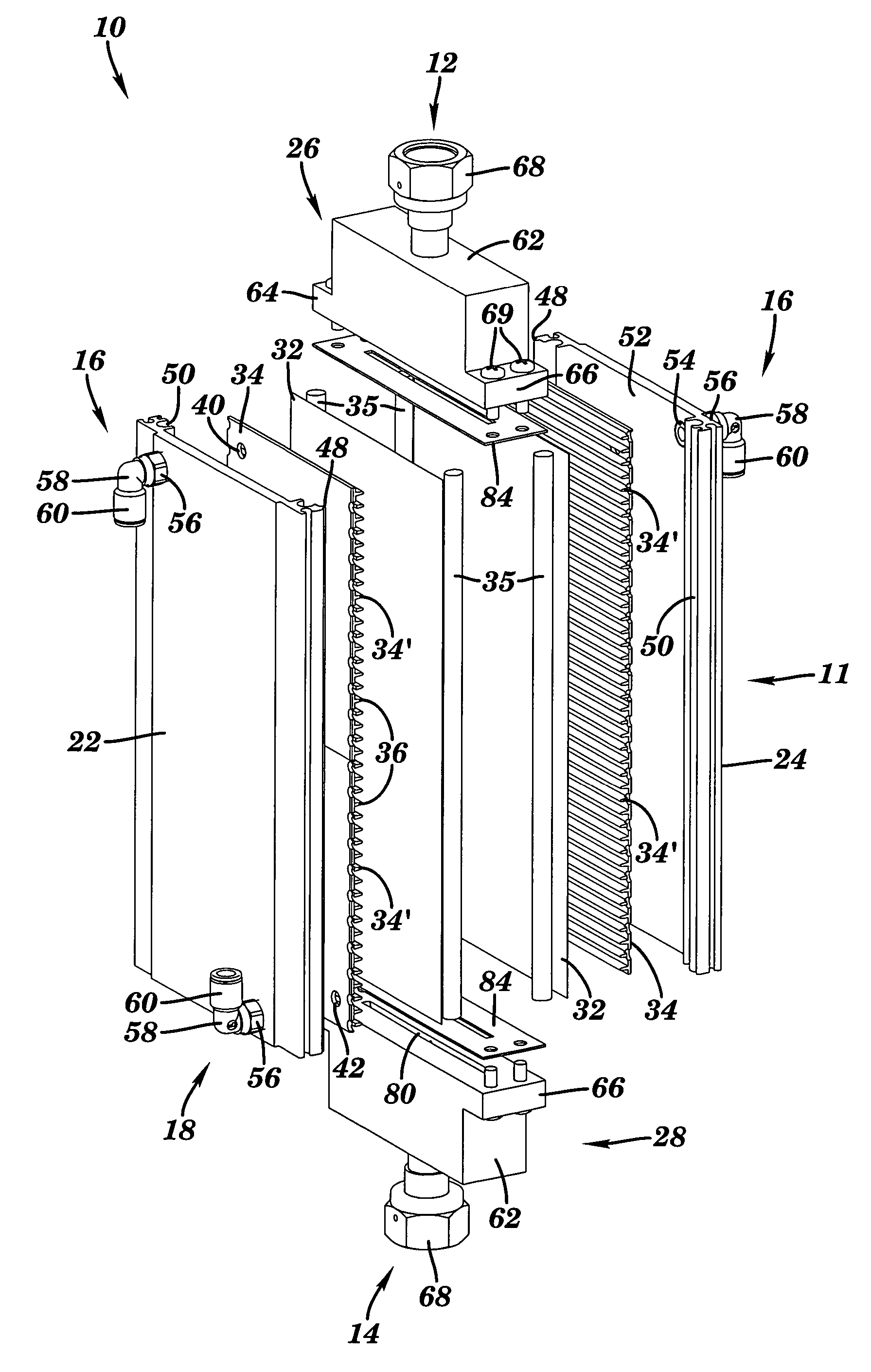
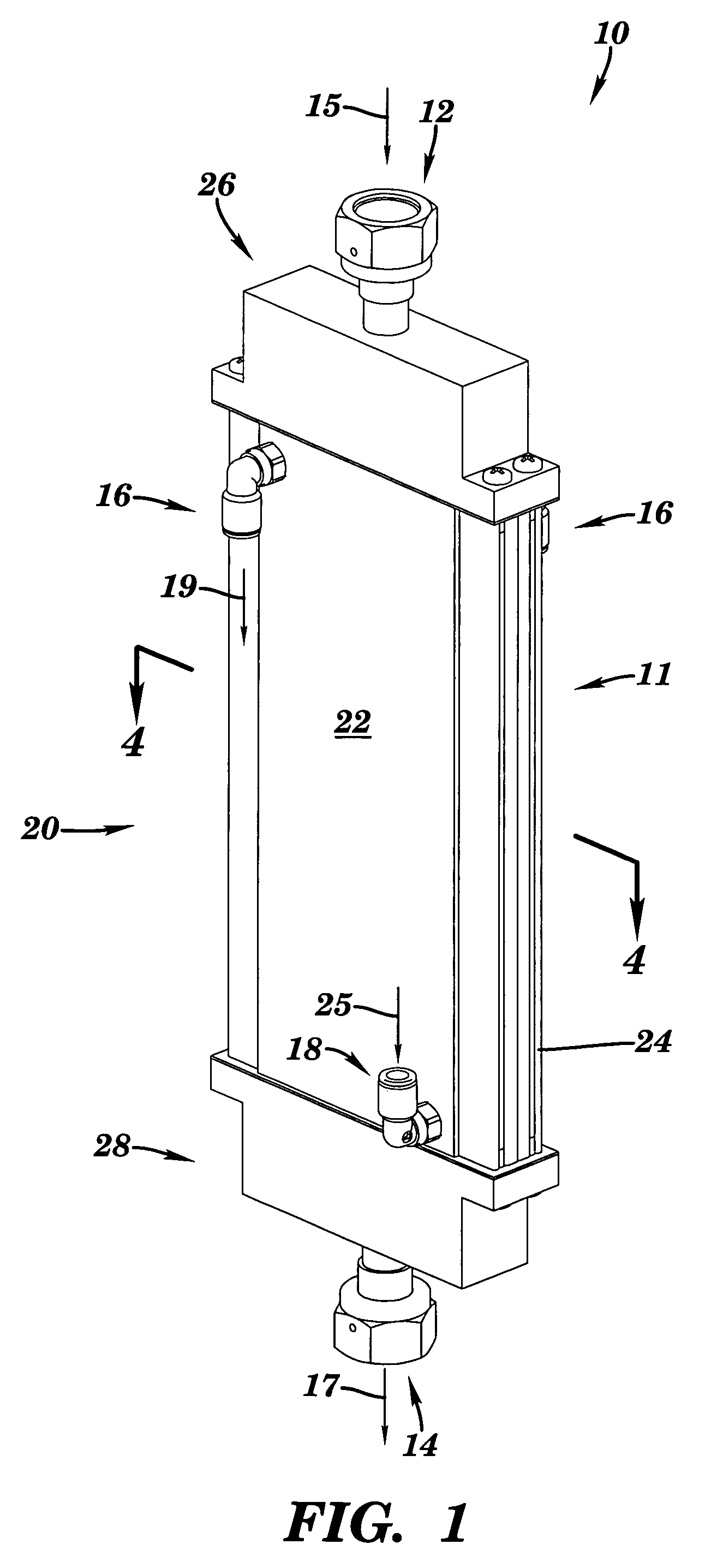
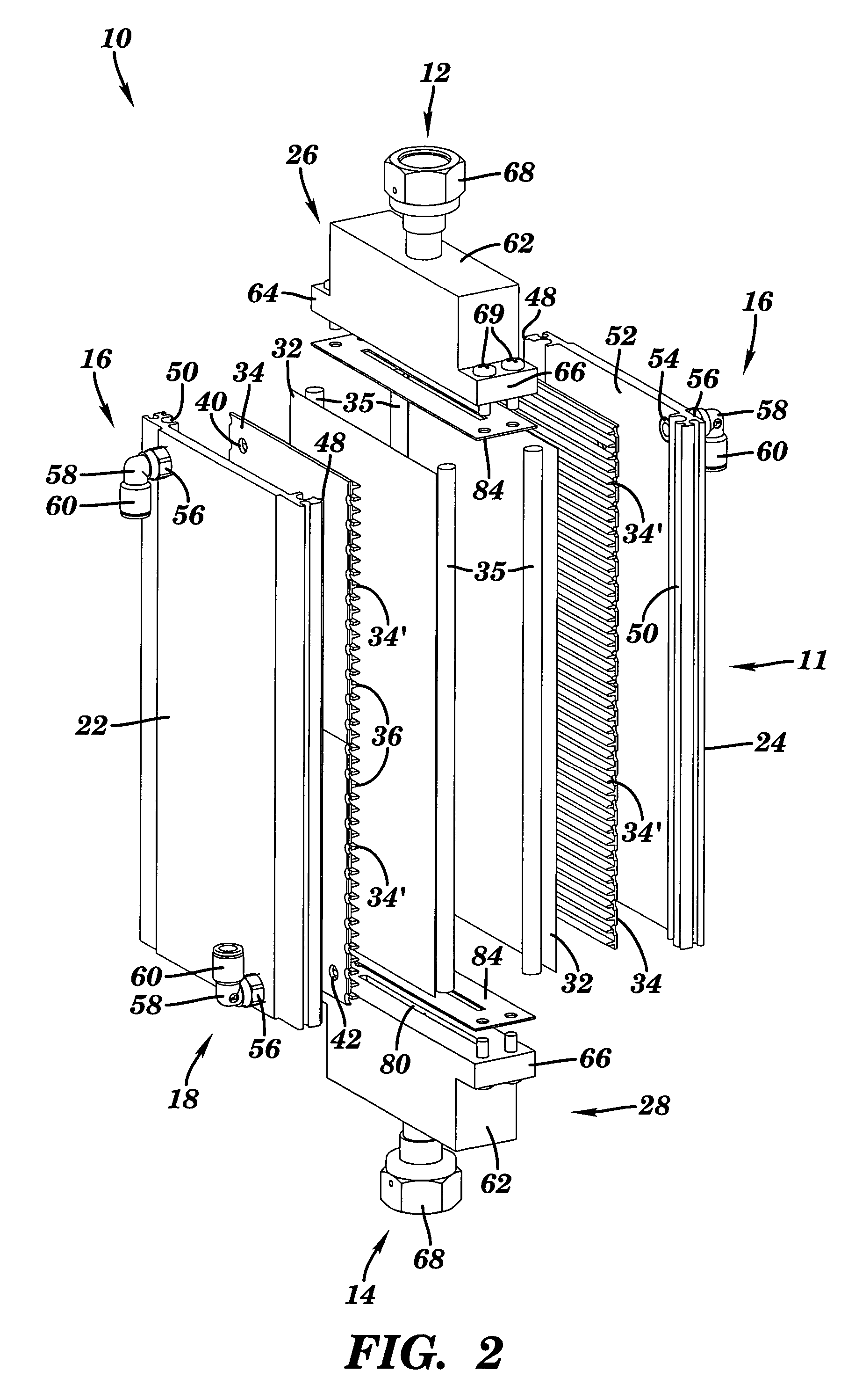
[0026]Aspects of the present invention provide methods and devices for removing water vapor from particulate-containing gas streams while minimizing the impact of the water vapor removal upon the particulate content of the gas stream. FIG. 1 is a perspective view of a parallel plate gas dehumidifier or dryer 10 according to one aspect of the invention. Dehumidifier 10 includes a housing 11, an untreated gas inlet 12, a treated gas outlet 14, one or more treatment gas outlets 16, and one or more treatment gas inlets 18. According to one aspect of the invention, untreated gas, indicated by arrow 15, having at least some water vapor, is introduced to gas inlet 12, passes through and is dehumidified in dehumidifier 10, and then the treated gas, indicated by arrow 17, is discharged from gas outlet 14. At the same time, a source of treatment gas, for example, a gas having less water vapor and / or less vapor pressure and / or less pressure than the gas 15 introduced to inlet 12, is introduced...


PUM


Abstract

A parallel-plate diffusion gas dehumidifier has a treatment zone having at least one water-permeable membrane. The gas dehumidifier includes an untreated gas inlet, a treatment zone bounded by water-permeable membranes, a support structure for the membranes, access to a source of vacuum, and a dehumidified gas outlet. The cross section of the treatment zone may be provided in various shapes, for example, rectangular. The gas dehumidifier inlet and outlet include flow transitions that minimize the obstruction of particles passing through the dehumidifier. The dehumidifier may be used in particle sampling systems to dehumidify the sample gas prior to introducing the sample gas to a mass measuring device and mass flow controller. Methods of operating the gas dehumidifier and the particle sampling system are also provided.

Description

TECHNICAL FIELD[0001]This invention relates generally to gas samplers, and more particularly to methods and devices for dehumidifying gas streams introduced to an apparatus for collecting and detecting particulate in a gas sample.BACKGROUND OF THE INVENTION[0002]Air borne particulate, either occurring naturally, such as pollen and dust, or generated through industry, such as smoke or automobile exhaust, can be hazardous to human health. Particulate concentration and content may typically be monitored to, among other things, evaluate the changes in particulate matter due to natural or industrial activity. Particulate sampling systems are typically used to collect and categorize the particulate content of ambient air. One typical particulate sampling system is provided by the Environmental Instruments Division of Thermo Electron Corporation of East Greenbush, N.Y. and described in U.S. Pat. No. 6,502,450, the disclosure of which is incorporated by reference herein in its entirety. The...

Claims


Application Information

Patent Timeline
Patent Type & Authority Patents(United States)
IPC IPC(8): B01D53/22
CPCB01D53/22B01D53/268B01D63/08G01N1/22B01D2317/04B01D2319/04G01N1/2205G01N2001/2267
Inventor PICCININI, JAMES DOMENICKBASCH, LAUREN R.BAILEY, ADAM
Owner THERMO ELECTRON A DE
Learn More